Lampert M280 Operating Manual Download Page 11


© Lampert Werktechnik GmbH


2017


10 

7. WELDING INSTRUCTIONS 


NOTE! 

PRIOR 

TO 

WELDING, 

ALWAYS 

CHECK 

THE 

FUNCTION  OF  THE  EYE  PROTECTION  FILTER  AS 
DESCRIBED  IN  CHAPTER  5.5  "FILTER  TEST".  IF  THE 
EYE  PROTECTION  FILTER  (SHUTTER)  FAILS  TO 

SWITCH  OVER  FROM  LIGHT  TO  DARK,  THEN  IT 
MUST 

BE 

IMMEDIATELY 

EXCHANGED 

BY 

SPECIALIST PERSONNEL


7.1 WELDING INSTRUCTIONS 

  First  connect  a  metallic  blank  section  of  the  workpiece 

with the contact clamp. 

  Lightly  touch  the  area  to  be  welded  with  the  tip  of  the 

electrode until welding begins. In doing so, it is important 

to  remain  in  the  position  where  initial  contact  is  made 
until  welding  begins,  i.e.  neither  to  follow  the  electrode 
with  the  workpiece  when  it  retracts  slightly  in  the 
handpiece, nor to pull back. 


APPLY EXTREMELY LIGHT PRESSURE OR NO PRESSURE TO THE TIP OF THE ELECTRODE! 
 

The welding process proceeds automatically: 

  shielding gas flows around the welding point. 

  A signal tone announces the arc. 


The  arc  triggers  and  the  electrode  retracts 

slightly  in 

the handpiece. 

  The shielding gas supply cuts off. 


THE WELDING PROCESS CAN BE HALTED AT ANY  TIME BY  MEANS OF LIFTING  THE ELECTRODE AWAY 
FROM THE WORKPIECE.


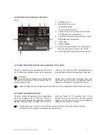
7.2 WELDING WITH FOOT SWITCH 

(optional accessory) 


With the „M280“ switched off, connect the foot switch to the 
socket (4) on the rear of the device. Switch the device on, 
wait  for  the  self-test  to  conclude  and  confirm  the  safety 

prompt by pressing any button. The device is now ready for 
operation. 

 
THE  FOOT  SWITCH  CAN  BE  ACTIVATED  BY  PRESSING  AND  HOLDING  IT  (APPROX.  2  SEC.).  A  WHITE  SYMBOL 
APPEARS IN THE DISPLAY. 
 

Connect  a  metallic  blank 
section of the workpiece with 
the  contact  clamp.  Now 

lightly  touch  the  workpiece  with  the  electrode,  so  that  the 

shielding gas flows out. If the foot switch is operated in this 
mode,  the  welding  process  will  start  automatically  as 
described in chapter 7.1. 

 
PRESSING AND HOLDING THE FOOT SWITCH (APPROX. 2 SEC.) (WITHOUT TOUCHING A WORKPIECE) CAUSES IT 
TO BE DEACTIVATED AND THE WHITE SYMBOL ON THE DISPLAY DISAPPEARS. 
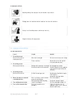


7.3 BASICS AND TIPS 

IMPORTANT! 

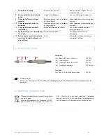
  Always work with a well sharpened electrode (see point 

7.4 for information about sharpening the electrodes).  

  Ensure  extremely  good  contact  between  the  workpiece 

and  the  contact  clamp,  i.e.  make  contact  between  the 
workpiece  and  the  connection  cable  terminal  at  a  point 
which is metallically blank. 

  Never weld "free hand", i.e. put your hands comfortably 

on  the  work  bench.  Shaking  hands  can  cause  the 
configured parameters to be falsified. 

  Apply only light force to the electrode tip. 

  Weld with the correct gas flow of 2 - 3 litres/minute and 

check this regularly.  

  With a little experience you will notice that the angle with 

which  you  touch  the  workpiece  with  tip  of  the  electrode 
affects the "direction of flow" of the welding point.  

  The  electrode  can  easily  be  clamped  in  somewhat 

longer for welding recessed areas.


In many cases it is helpful to work with welding wire as a 
welding supplement, but never with solder. 


Summary of Contents for M280

Page 1: ...Operating manual M280 TIG pulse welding device 8...

Page 2: ...SE THE MANUFACTURER ACCEPTS NO LIABILITY FOR DAMAGES CAUSED THROUGH INAPPROPRIATE USE AND IMPROPER OPERATION THE GENERAL SAFETY REQUIREMENTS AND PERSONAL BODY PROTECTION CHAPTERS MUST BE READ BEFORE C...

Page 3: ...ion of the onscreen symbols Pg 9 7 WELDING INSTRUCTIONS 7 1 Introduction for welding Pg 10 7 2 Welding with foot switch Optional accessory Pg 11 7 3 Basics and tips Pg 12 7 4 Resharpening the electrod...

Page 4: ...dertaking any work on the system beyond minor manipulations where it is necessary to leave the workplace even for brief periods The highest and thus the most dangerous voltage in the welding circuit i...

Page 5: ...NATION Never look into the LED lamp or its reflections without eye protection use protective shield or safety glasses with suitable protective glass SMOKES AND GASES When welding especially in small s...

Page 6: ...coupling nut hand tight WARNING ONLY SUITABLE ORIGINAL EYE PROTECTION SYSTEMS FROM LAMPERT MAY BE CONNECTED TO THE WELDING SYSTEM OTHER EYE PROTECTION SYSTEMS ARE NOT APPROVED AND CAN LEAD TO PERMANE...

Page 7: ...e connector of the handpiece as straight as possible into the socket Fig 27 p 7 on the front of the M280 and fasten in place by tightening the coupling nut hand tight in a clockwise direction Insert t...

Page 8: ...ps DISPLAY 30 Material or welding program 31 Preselected welding situation geometry 32 Power output as a percentage 33 Foot switch display optional 34 Pulse duration in milliseconds ms 5 2 EXPLANATION...

Page 9: ...is correctly adjusted quit the Gas Test by pressing the corresponding button 5 5 OPERATING LEVEL SETTINGS The Settings user level can be used to modify basic settings and launch various test function...

Page 10: ...y thin materials or wires it is recommended to use a shorter welding time primarily when welding near to heat sensitive materials Welding times of no more than 4 ms are recommended here With copper al...

Page 11: ...ety prompt by pressing any button The device is now ready for operation THE FOOT SWITCH CAN BE ACTIVATED BY PRESSING AND HOLDING IT APPROX 2 SEC A WHITE SYMBOL APPEARS IN THE DISPLAY Connect a metalli...

Page 12: ...requires a minimum of maintenance under normal working conditions However it is essential that a few points are observed in order to guarantee the functionality and to keep the spot welding device ful...

Page 13: ...eight 230 V 50 60 Hz 10 T 3 15 A 400VA 30 43 V 43 V 80 0 8 s min ARGON 99 996 4 bar I B IP 21S 6 5 kg 9 2 TYPE PLATE Explanation of pictographs Current Voltage Protection type Hertz Alternating curren...

Page 14: ...ue to leakage current Switch device off and back on again If fault reoccurs arrange for servicing of device 4 Mains fuse blows or automatic circuit breaker trips Mains insufficiently fused or incorrec...

Page 15: ...ecial local conditions Use special foot mat for the workspace 13 Device begins to weld immediately when touching the workpiece no gas pre flow Fault Immediately shut down the device arrange for servic...

Page 16: ...17 15 13 EC DECLARATION OF CONFORMITY Please find enclosed to this shipment the separate document Declaration of Conformity Text and illustrations represent the technical status at the time of printin...

Page 17: ...are searching for one or another tip on working with your M280 Then just sign up for our newsletter on www lampert info VISIT OUR SHOWROOM Our video library is showing many applications from everyday...

Page 18: ...Born in Germany Lampert Werktechnik GmbH Ettlebener Stra e 27 D 97440 Werneck Tel 49 9722 9459 0 mail lampert info www lampert info Rev 1 0...

Reviews: