background image

12 


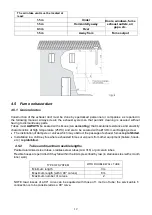
The air intake vent must be located at 

least: 


1.5 m 

Under 

Doors, windows, fume 

exhaust outlets, air 

gaps, etc. 

1.5 m 

Horizontally away 

0.3 m  

Over 

1.5 m 

Away from 

Fume output 


4.5  Fume exhaust duct 


4.5.1  General notes 


Construction of the exhaust duct must be done by specialised personnel or companies, as reported in 

the following manual. Always create the exhaust system so that periodic cleaning is assured without 

having to dismantle any parts. 

Tubes must 

ALWAYS 

be sealed with silicone (

no cementing

) that maintains resistance and elasticity 

characteristics at high temperature (250°C) and are to be secured with a Ø3.9mm self-tapping screw. 

  The installation of dampers or valves which may obstruct the passage of exhaust fumes 

is prohibited

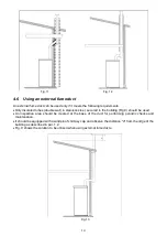
  Installation in a chimney flue where exhausted fumes or vapours from other equipment (boilers, hoods, 

etc.) 

is prohibited


4.5.2 

Tubes and maximum usable lengths 

Painted aluminized steel tubes, stainless steel tubes (Aisi 316) or porcelain tubes. 

Flexible hoses are permitted if they fall within the limits prescribed by law (in stainless steel with smooth 

inner wall).  


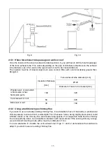
TYPE OF SYSTEM 

WITH DOUBLE-WALL TUBE 

Minimum length 

3 m 

Maximum length (with 3 90° curves) 

8 m 

Maximum number of curves 


NOTE: load losses of a 90° curve can be equated with those of 1 metre of tube; the serviceable T- 

connection is to be considered as a 90° curve. 


Summary of Contents for Jessica Natural SN

Page 1: ...e The instruction manual is an integral part of the product Laminox S r l reserves the right to change the characteristics and data reported in the following document at any time and without warning i...

Page 2: ...gloves to avoid leaving difficult to remove fingerprints for the first cleaning Stove installation must be performed by at least two people Connect the stove to the mains only after proper profession...

Page 3: ...nces for positioning air intake vents Non hermetic installation 11 4 5 Fume exhaust duct 12 4 6 Using an external fume duct 14 5 ASSEMBLY 15 5 1 General notes 15 5 2 Unpacking 15 6 USE 15 6 1 Componen...

Page 4: ...xhaust pipe of the stove and a height no less than the one stated see table 2 Never use two stoves a fireplace and a stove a stove and a wood stove etc in the same room since the draft of one could da...

Page 5: ...tructed so as to prevent penetration into the flue of rain snow or foreign bodies and so that in the event of winds in any direction and at any angle it assures the discharge of combustion products wi...

Page 6: ...ts set out in the paragraphs above The adjacent room cannot be used as a garage for storage of combustible material or for activities involving a risk of fire 1 4 External air intake vent Hermetic ins...

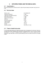
Page 7: ...ncy 88 5 Recommended draft 3 6 Pa Hopper capacity 15 Kg Smoke outlet 120 mm Weight 114 Kg Dimension LxPxH 572 x 553 x 1151 mm 2 3 Product identification data The technical label shows device data and...

Page 8: ...and horizontal splits Since pellet characteristics and quality greatly influence the autonomy efficiency and proper operation of the stove we recommend AVOID using pellets with dimensions different fr...

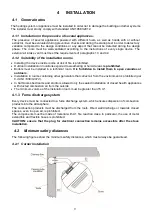
Page 9: ...d Boilers must be installed in a technical room It is forbidden to install them in open verandas or outdoors Installation in rooms containing other generators that collect air from the environment is...

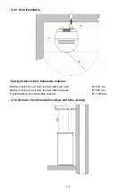
Page 10: ...lammable material Minimum distance in air from the flammable rear wall P 200 mm Minimum distance in air from the flammable side wall P 200 mm Frontal distance from flammable material R 1000 mm 4 2 3 D...

Page 11: ...and have a thickness of at least 2 mm Fig 5 and 6 Fig 5 Fig 6 4 4 Minimum distances for positioning air intake vents Non hermetic installation Pellet stove combustion air intake vents cannot be connec...

Page 12: ...50 C and are to be secured with a 3 9mm self tapping screw The installation of dampers or valves which may obstruct the passage of exhaust fumes is prohibited Installation in a chimney flue where exha...

Page 13: ...ich is flammable or has flammable parts 100 320 Concrete wall or roof 50 220 Brick wall or roof 30 180 4 5 4 Using a traditional type chimney flue If you wish to use an already existing chimney flue i...

Page 14: ...s steel secured to the building Fig 9 should be used An inspection area should be created at the base of the duct for performing periodic checks and maintenance It should be equipped with a windproof...

Page 15: ...other than that for which it was designed No other fuel besides wood pellets must be used Do not use liquid fuels When the stove is turned on it can reach extremely high temperatures to the touch esp...

Page 16: ...unburned pellets IMMEDIATELY TURN OFF the stove and contact the service centre CAUTION pay the utmost attention when children are present to prevent them from standing in front of the stove 6 1 Compo...

Page 17: ...end until the brazier is filled 2 Lift the pin located on the top of the stove using the starting lever provided and turn it to the locked position Fig 21 22 Fig 21 Fig 22 CAUTION Always remove the st...

Page 18: ...on Max Minimum power position Min Fig 25 6 5 Shutdown By moving the lever in position 1 fig 21 the fall of pellet into the brazier will stop combustion will continue for about 20 minutes after which t...

Page 19: ...or otherwise locally dispersed they should be retained in the closed container until all conders have been thoroughly cooled CAUTION ashes keep embers on for a long time 7 3 Brazier cleaning When the...

Page 20: ...tened with water to clean metal stove parts Never clean metal or ceramic parts with alcohol thinners petrol ketones or other degreasers Use of these substances frees the company from all liability Dis...

Page 21: ...Clean fans thoroughly 7 13 Routine and special maintenance These operations should be programmed ANNUALLY with a Technical Assistance Centre and are necessary to ensure the maintenance of product eff...

Page 22: ...22...

Page 23: ...23...

Page 24: ...Laminox S r l Hydro Division Zona Industriale Callarella 261 263 62028 SARNANO MC Italy Tel 39 0733 657 622 Fax 39 0733 657 494 www laminox com e mail export laminox com Jessica SN rev 07 2022...

Reviews: