


O & M Manual – Insulated Case ATS Rev: October 2020
Publication Number:
MN0100700E
Version: V10.01.20
Page 53
7.
Troubleshooting Guide
This guide is intended to assist an individual with a basic understanding of electrical circuitry to
troubleshoot an automatic transfer switch as manufactured by Lake Shore Electric Corporation.
Any questions relating to the use of this Manual should be referred to the Service Department of
Lake Shore Electric Corporation, 205 Willis Street, Bedford, Ohio 44146, Phone (440) 232-0200,
Fax (440) 232-5644.
CAUTION: WHEN WORKING ON EQUIPMENT OF THIS TYPE, EXTREME DANGER FROM
ELECTRICAL HAZARDS EXITS. DO NOT ATTEMPT ANY REPAIRS OR ADJUSTMENTS TO
THIS EQUIPMENT WITHOUT TAKING EVERY PRECAUTION TO PREVENT AN ACCIDENT.
WARNING!
IN INSTALLATION AND USE OF THIS PRODUCT, COMPLY WITH THE NATIONAL
ELECTRICAL CODE, FEDERAL, STATE AND LOCAL CODES, AND ALL APPLICABLE
SAFETY CODES. IN ADDITION, TURN OFF POWER AND TAKE OTHER NECESSARY
PRECAUTIONS TO PREVENT PERSONAL INJURY AND EQUIPMENT DAMAGE.
WHEN WORKING ON EQUIPMENT OF THIS TYPE, EXTREME DANGER OF
ELECTROCUTION EXISTS. THIS MAY RESULT IN INJURY OR DEATH. DO NOT ATTEMPT
ANY REPAIRS OR ADJUSTMENTS TO THIS EQUIPMENT WITHOUT FIRST TAKING EVERY
PRECAUTION TO PREVENT ACCIDENTAL INJURIES.
The following conditions MUST be met before attempting to troubleshoot a molded case transfer
switch:
1.
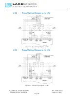
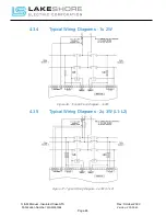
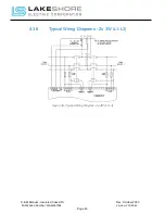
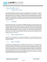
A wiring diagram for the switch must be available.
2.
Normal and Emergency voltage and frequency must be available and within the correct
operating limits.
3.
Control circuit voltage (if transformers are used) must be 110 to 125 volts on their
secondary side.
4.
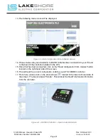
Verify the readings on the LSE8600 are correct for system voltage. If they are not as
expected, measure the voltage directly at the incoming terminals to the ATS. Use all
appropriate caution necessary when performing those measurements.
a.
Check wiring to the LSE8600 controller if direct measurements are correct.
Possible bad controller if wiring checks out "OK".
5.
All timers must be turned down or considerations given to them while the tests are being
conducted. (i.e.: Return Delay)
6.
If trip units are included in the switch, they must be reset if previously tripped due to an
overload.
7.
All electrical connections must be tight and in accordance with the wiring diagram.
8.
All components must be free of obvious defects apart from normal usage.
9.
The switch must be connected to a good earth ground.


