


O & M Manual – Insulated Case ATS Rev: October 2020
Publication Number:
MN0100700E
Version: V10.01.20
Page 52
6.
Molded Case Switches
6.1.
General Information
The molded case switches used in transfer switches are the standard devices supplied by molded
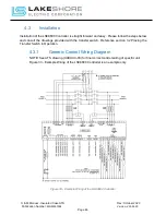
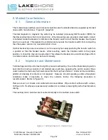
case switch manufactures. Figure 41 (page 52).
Thermal magnetic or magnetic trip units may be installed (Accessory CBTN and/or CBTE) for
thermal overload and short circuit protection. When these trips are provided, a bell alarm contact
is included inside the breaker to indicate to the transfer switch circuit that the breaker has tripped
due to an overload. This signals the controller and prevents the transfer switch from connecting
the other power source into a potential short circuit.
If either breaker trips due to overload, it can be reset by manually operating the transfer switch to
a position so that the breaker resets. After resetting, return the transfer switch to the proper
position. A shunt trip may also be provided. This allows the breaker to be electrically tripped from
a remote location and can also be reset manually.
6.2.
Inspection and Maintenance
Terminal lugs and trip units must be tight to prevent overheating. Due to the inherent wiping action
built into the moving contacts of all molded case switches, operating the switch several times
under load will remove any high resistance film that may have formed. Under normal conditions,
additional cleaning of contacts is not required. However, should operating and/or atmospheric
conditions make it desirable to clean the contacts further, the following procedure is
recommended. (Refer to Figure 41).
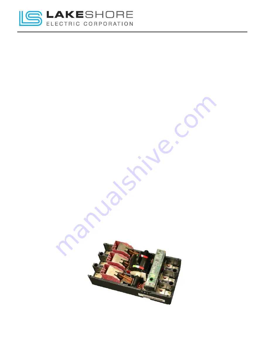
Remove cover, arc chutes, and cable terminal assemblies. Wipe contact surfaces with a clean,
lint free cloth. If surfaces are excessively oxidized or corroded, scrape lightly with a fine file before
wiping.
The auxiliary micro switches are mounted internally to the molded case switch.
Figure 41 - Molded Case Unit - Internal View


