Lake Shore Model 1015 User’s Manual
Installation
2-3
2.5
RACK MOUNTING
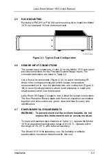
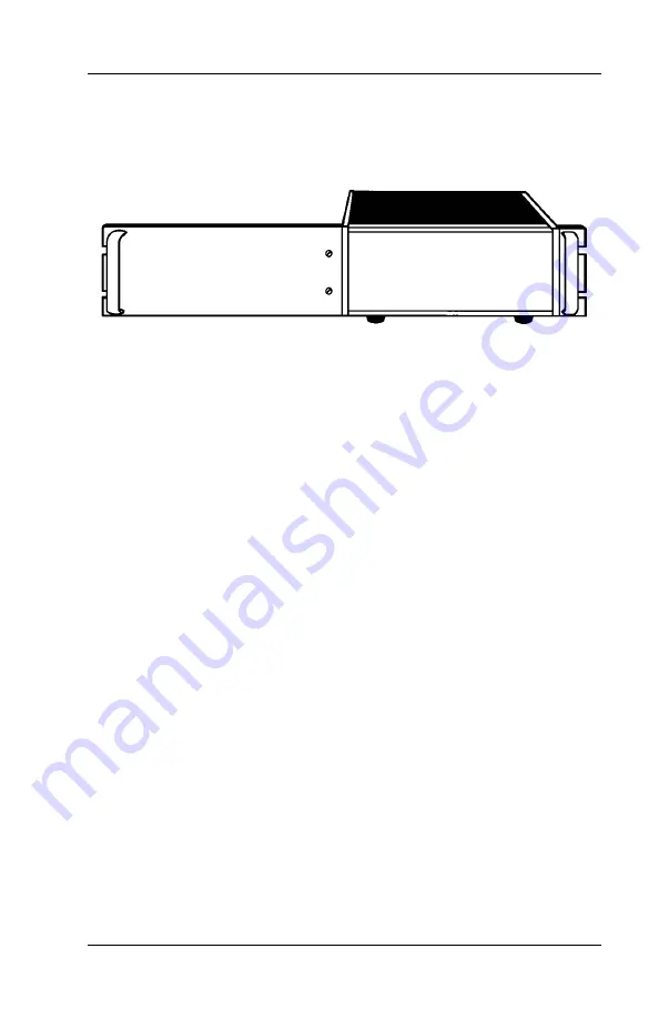
Purchase a PM-3H1 or PM-3H2 rack mounting kit to install the Model
1015 in a standard 19-inch instrument rack.
P-1015-2-1.bmp
Figure 2-1. Typical Rack Configuration
2.6
SENSOR INPUT CONNECTIONS
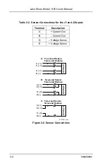
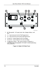
The sensor input connectors J1 and J2 on the Model 1015 rear panel
provide connections for the First and Second Stage inputs. The
connector definitions are listed in Table 2-2.
Use a four-wire connection (Figure 2-1A) to avoid introducing IR
drops in the voltage sensing pair which causes temperature
measurement error. Use the alternate two-wire connection (Figure 2-
1B) in less critical applications where lead resistance is small and
small readout errors can be tolerated.
Lake Shore 36-Gauge Cryogenic wire is ideal for sensor connections.
The four Phosphor Bronze leads with Formvar insulation are bonded
together and color-coded red, green, clear and blue for easy wire
identification.
2.7
ENVIRONMENTAL REQUIREMENTS
WARNING: To prevent electrical fire or shock hazards, do not
expose this instrument to rain or excess moisture.
To meet and maintain specifications in Table 1-1, operate the Model
1015 at an ambient temperature range of 23 ±5 °C. Operate within
the range of 15
–
35 °C with reduced accuracy.
The Model 1015 is for laboratory use. No humidity or altitude
specifications have been determined for this unit.


