background image

WB50NBT 

Quick Start Guide 

Embedded Wireless Solutions Support Center: 


http://ews-support.lairdtech.com 

www.lairdtech.com/wi-fi


© Copyright 2016 Laird. All Rights Reserved


Americas: +1-800-492-2320 

Europe: +44-1628-858-940 

Hong Kong: +852 2923 0600


Additional Required Equipment 

Qty. 

Item 

Small Philips head jeweler’s screw driver 

USB to RS232 DB9/DB25 cable 

CAT 5 e cable (optional) 

USB A to USB B cable (optional) 

Hardware Installation and Configuration 

To assemble the WB50NBT evaluation kit, follow these steps: 

Note:   To prevent damage, you must connect the U.FL ultra-micro coax cables to the connectors on the 

WB50NBT prior to fitting the WB50NBT to the BB40NBT evaluation board. 

1.


Using the four nuts provided, attach the four standoffs to the underside corners of the BB40NBT board. 

2.


Before fitting the WB50NBT to the BB40NBT evaluation board, turn the WB50NBT so that the 120 way is 
on the underside of the board. 

3.


Connect the dual band antennas with an SMA connector to each of the AUX. ANT and MAIN ANTENNA 
SMA connectors on the top side of the BB40BNT board

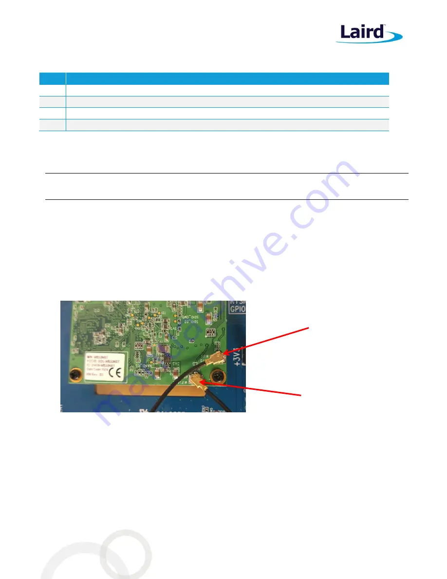
Figure 1

 shows the location of the Wi-Fi and Wi-Fi 

/Bluetooth antennas. This information is also available on the silk screen on the WB50NBT.  

4.


Plug the WB50NBT module into the 120-pin high-density Kyocera connector situated near the central 
aperture on the BB40NBT breakout board making sure to feed the two SMA connectors on the ends of the 
U.FL coax cables through the aperture in the BB40NBT breakout board. 


Figure 1: Location of the Wi-Fi and Bluetooth U.FL connectors on the SDB-WB50NBT 

5.


Using the small Philips head jeweler’s screw driver, secure the WB50NBT to the BB40NBT board using the 
three small Philips screws.  

6.


Feed the SMA connector connected to the ANT0 WI-FI to the aperture marked MAIN ANTENNA on the 
BB40NBT board and, using the provided nuts and washers, secure the SMA connector to the BB40NBT 
board.  

7.


Repeat for the ANT1 Wi-Fi and BT SMA, this time to the aperture marked AUX. ANT on the BB40NBT 
board.  

You can power the BB40NBT from mains power using the 12v power pack provided. 

Figure 2

 shows the DC 

jack and the power switch. Ensure the power switch is set to Off.  

Wi-Fi only antenna 
cable connected to 
U.FL connector 

Wi-Fi and BT antenna cable 
connected to U.FL connector 

Summary of Contents for WB50NBT

Page 1: ...A Quick Start Guide WB50NBT Version 1 1...

Page 2: ...t lairdtech com www lairdtech com wi fi 2 Copyright 2016 Laird All Rights Reserved Americas 1 800 492 2320 Europe 44 1628 858 940 Hong Kong 852 2923 0600 REVISION HISTORY Version Date Notes Approver 1...

Page 3: ...ntroduction to the Laird WB50NBT 4 Product Description 4 Quick Start Guide WB50NBT 4 Inventory of Equipment 4 Additional Required Equipment 5 Hardware Installation and Configuration 5 Basics of the BB...

Page 4: ...oexistence scheme a fully integrated security supplicant providing 802 11i WPA2 Enterprise authentication and data encryption and a BT protocol stack The system is a full Linux 4 1 13 kernel based sys...

Page 5: ...the top side of the BB40BNT board Figure 1 shows the location of the Wi Fi and Wi Fi Bluetooth antennas This information is also available on the silk screen on the WB50NBT 4 Plug the WB50NBT module i...

Page 6: ...made available on the BB40NBT shown in Figure 3 Additional information regarding all interfaces their use and configuration is available in the WB50 Reference Guide This guide is accessible from the W...

Page 7: ...Initial Serial Communication with the WB50NBT The following items are used in this section Qty Item 1 BB40NBT breakout board with WB50NBT module fitted as described above 1 USB to RS232 cable 1 Power...

Page 8: ...Control None Start Communication with the WB50NBT from the Host Connect the 12v power supply to the wall outlet and the barrel connector to the SC jack on the BB40NBT breakout board Slide the power sw...

Page 9: ...l need to be configured manually to match the following Address 192 168 3 2 Netmask 255 255 255 0 Gateway 192 168 3 1 DNS servers 8 8 8 8 Once the connection to the WB50NBT has been established an ssh...

Page 10: ...following Status Not Associated Config name Default SSID Channel 0 RSSI 0 Device Name MAC 00 17 23 e0 38 e4 IP 192 168 1 1 IPv6 AP Name AP MAC Bit Rate auto Tx Power 0 mW Beacon Period 0 DTIM 0 To ex...

Page 11: ...grated laird WebLCM via the Ethernet or g_ether USB connection See the Web LCM Linux Platform Application Note for information This documentation is available from the Documentation tab of the Laird W...

Page 12: ...o either interface is echoed out from the opposite interface See the WB50 smartBASIC Extensions guide and the WB50NBT Reference Guide for more information These documents are available from the Docume...

Page 13: ...Kong 852 2923 0600 Directory Content of note Comment etc init d opt optional startup scripts Create a symlink to the item to be started ln s etc init d opt name of script etc init d etc ssl default w...

Reviews: