


www..lairdconnect.com/wireless
20
© Copyright 2020 Laird Connectivity. All Rights Reserved
Americas
: +1-800-492-2320
Europe
: +44-1628-858-940
Hong Kong
: +852 2923 0610
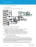
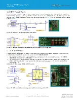
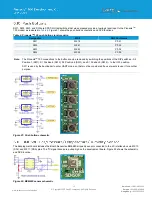
The VIN to the modem can be sampled by enabling (1.8V logic) modem pin M2.55 (P0.28), VIN_ADC_EN and then taking
ADC measurements using modem pin M2.53 (P0.29), shown in Figure 23.
Figure 23: VIN monitor schematic
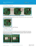
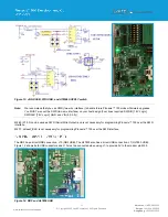
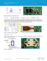
The DVK includes a GPS antenna shown in Figure 24
that is connected to the modem using J23 and a U.FL to U.FL cable.
Figure 24: GPS antenna
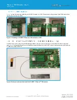
Figure 25 shows a removable jumper (on J4) which is provided to break the power supply line directly to the modem, allowing
the measurement of the Pinnacle
TM
100 current consumption.
For normal operation, the jumper on J4 must be fitted (and is fitted by default).
Summary of Contents for 453-00010-K1
Page 1: ...Version 1 0 ...


