


www..lairdconnect.com/wireless
11
© Copyright 2020 Laird Connectivity. All Rights Reserved
Americas
: +1-800-492-2320
Europe
: +44-1628-858-940
Hong Kong
: +852 2923 0610
™ 100 development board power supply block diagram.
D6
J7 HL7800
micro USB
J10 NRF
micro USB
J18 JLINK
micro USB
J30 FTDI
micro USB
J17
DC JACK
J6
Bench
D2
D3
D7
D1
Q1
V
IN
_D
C
V
_
U
SB
2P 2T S witc h
2A
1A
1C
2C
1B
2B
SW6
Power
ON/OFF
D8
D5
Buck-Boost
Regulator
VIN_ADC
To M2.53
J22
4AA
J2
2AA
Q2
Q3
D4
3.3V
Regulator
1.8V
Regulator
J4
3.3V
1.8V
2
P
4T
S
w
itc
h
1
2
3
4
5
6
12
11
10
9
8
7
4A
A
2A
A
SW7
Source Select
Load
Switch
M2_VIN
Load
Switch
Load
Switch
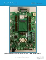
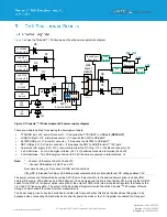
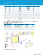
Figure 9: Pinnacle
™ 100 development kit power supply diagram
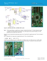
There are multiple options for powering the development board:
▪
FTDI USB port, J30, micro-B connector
– If it requires the FTDI UART to USB path (
DEFAULT)
▪
JLINK USB port, J18, micro-B connector
– If it requires the SWD to USB path*
▪
HL7800 USB port, J7, micro-B connector
– If it requires the HL7800 to USB path**
▪
NRF USB port, J10, micro-B connector
– If it requires the NRF to USB (Pinnacle™ 100) path
▪
An external DC supply (4.4V-12V), connected to either the DC Plug, J17, or the Bench connector, J6
▪
4 x AA batteries
– Four AA Energizer Lithium (4.4-7.2V) batteries connected to terminal block, J22
▪
2 x AA batteries
– Two AA Energizer Lithium (2.2-3.6V) batteries connected to terminal block, J2
Note:
*
– Connect USB cables to both J18 and J30
**
– Connect USB cables to both J7 and J10
Recommend using a 1A or above for USB port connections
VIN_ADC is intended for 2AA or 4AA battery measurement and is not intended for ext DC voltages above 7.2V.
The power sources are first selected by setting SW7 (Source Select switch) to the desired power option (includes USB,
external DC supply, 4AA batteries, and 2AA batteries). The selected power option is then fed into SW6, which is the ON/OFF
switch for the DVK. For all power option, except 2AA, the output of SW6 is fed into a Buck-Boost regulator that feeds both a
1.8V and 3.3V linear regulator. The output of the Buck-Boost Regulator is also fed to the Pinnacle
TM
100 modem VIN pins
through J4 which allows for modem current measurements.
The Power supply circuit uses load switches to isolate nets from each other, this allows the Buck-Boost Regulator to be
bypassed when connecting 2AA batteries and to directly power the modem, the 1.8V regulator is enabled for IO support.
Summary of Contents for 453-00010-K1
Page 1: ...Version 1 0 ...


