background image

Operator's Manual – 

Slam'N'Jam  


© 

LAI GAMES


Page 65 


For More Information, Visit BMI Gaming | www.bmigaming.com | (800) 746-2255 | +1.561.391.7200

Summary of Contents for Slam'N'Jam

Page 1: ...machine Keep this manual for your reference Go to www LAIGames com click on Operator Access to register your games and receive of future updates PLEASE NOTE V 2 5 For More Information Visit BMI Gamin...

Page 2: ...BOARD 12 STEP SIX ATTACHING BACKBOARD 12 STEP SEVEN ATTACHING TOP PANEL 13 STEP EIGHT ATTACHING BALL HOOP TO BACKBOARD 14 STEP EIGHT ATTACHING BALL HOOP TO BACKBOARD 14 STEP NINE FITTING BALL SENSOR 1...

Page 3: ...ING 40 GAME POWER UP SEQUENCE 42 TROUBLESHOOTING THE LINK SYSTEM 43 ERRORS AND TROUBLESHOOTING 45 ERROR CODE QUICK REFERENCE TABLE 45 TROUBLESHOOTING GAME ERRORS 46 FUSE INFORMATION 47 FUSE LOCATION D...

Page 4: ...Game Cabinet outdoors or in areas of high humidity direct water contact dust high heat or extreme cold Do Not install the Game Cabinet in areas that would present an obstacle in case of an emergency...

Page 5: ...ections for the integrated circuit IC logic PC Boards and other connectors Insufficient insertion can damage the electrical components Only qualified personnel should inspect or test the integrated ci...

Page 6: ...ing potential DESCRIPTION The Slam N Jam is a single player basketball game with linking capabilities Players use their skill and accuracy to throw as many balls through the basketball hoop as they ca...

Page 7: ...ric supply The supply must be a three wire grounded supply LOCATION REQUIREMENTS Ambient temperature between 5 C and 40 C Ambient humidity Low Ambient U V radiation Very low Vibrations level Low CAUTI...

Page 8: ...our country before applying power TIPS for Assembling Slam N Jam We recommend using two people when assembling Slam N Jam While one person is able to do most of the assembly using two people will be m...

Page 9: ...o people will be much easier A stepladder will also be very handy during assembly Unpack the machine and be sure to check that all parts are present As a quick reference refer to the photos on Page 7...

Page 10: ...the Slam n Jam This will assist you in locating the parts more easily BACK BOARD PANEL TOP PANEL 1ST BARRIER 2ND BARRIER HARDWARE PACK HOOP REAR PLAYFIELD BALL GATE ASSEMBLY BRACES BRACKET REAR RIGHT...

Page 11: ...wo front frames two of the Rubber Feet Frame Glides supplied Firmly bolt the two front side frames onto the game cabinet using the four M6 x 50mm Allan head bolts eight washers and four M6 locknuts su...

Page 12: ...m for easier assembly To help in alignment of panels don t tighten bolts until most of the assembly is completed Don t place the bolts in the third hole from the bottom this is for the barrier mesh NO...

Page 13: ...Rear Frame Braces on top of the rubber leveling feet using the four M12 nuts and spring washers supplied Refer to picture below for detail REAR BRACE MIDDLE BRACE NOTE Be sure to check AND TIGHTEN ALL...

Page 14: ...y Field Fit the rear playfield to the rear side frames and bolt in place using the six M6 x 50mm Knockdown bolts washers and Nylon lock nuts supplied Hardware found in Playfield Pack from Cashbox For...

Page 15: ...nel NOTE It is faster with two people for this part of the assembly Fit the backboard and bolt in place using the Ten M6 x 50mm Knockdown bolts washers Nylock nuts supplied Hardware found in Backboard...

Page 16: ...MES Page 13 STEP SEVEN Attaching Top Panel Attach the top panel to the two rear side panels using the eight M6 x 50mm washers and Nylock nuts supplied For More Information Visit BMI Gaming www bmigami...

Page 17: ...y attach the ball hoop to the backboard using the four M8 x 45mm bolts and washers supplied STEP NINE Fitting Ball Sensor Fit the electronic sensor through the hole in the backboard and plug in to the...

Page 18: ...ELEVEN Fitting the 1st barrier and 2nd barrier Attach the barrier panel assembly at the top bolt holes using the two M8 x 30mm bolts flat washers spring washers and nuts supplied Next attach at the b...

Page 19: ...and clip the conduit cover firmly in place Attach the adjustable noise dampener bracket to the backboard with the two 8mm x 20mm bolts and flat washers provided and adjust so playfield is tight up ag...

Page 20: ...using four bolts M8 x 30 mm washer spring washer and nuts supplied HINTS You may need to pull the frames together to align the holes on the frame to the ball gate assembly To help in alignment of pan...

Page 21: ...he cable rail cover on each side of the back front playfield and on the back of rear playfield also on the back panel Put all the cable into the cable rail close the cable rail cover make sure all the...

Page 22: ...and also easy installation we put the supporting bracket as per following photos When you receive the machine you should reposition the supporting bracket as following photo Unscrew the bracket reposi...

Page 23: ...s Manual Slam N Jam LAI GAMES Page 20 COMPLETE ASSEMBLED MACHINE CAUTION BE SURE TO CHECK MAINS VOLTAGE AND TEST BEFORE USAGE For More Information Visit BMI Gaming www bmigaming com 800 746 2255 1 561...

Page 24: ...button light will stay on and the game will say Waiting for more players A 10 second count down will allow time for extra players to join in the competition If the SOLO button selected the button lig...

Page 25: ...no coins are necessary COIN PLAY The Coin Play mode is entered from Attract mode by inserting coins in any of the two coin slots on the front of the machine cabinet then following the instructions in...

Page 26: ...s are made to the game for approximately four minutes it will automatically RETURN to Attract Mode PROGRAMMABLE ADJUSTMENTS MODE PLAY MODE The Display counts all Lamps are flashing and Sound is played...

Page 27: ...will be displayed on the 3 digit display If no switches are active then C 0 0 will be displayed CODE DISPLAY SWITCH FUNCTION SWITCH LOCATION C0 C 0 0 No Switch Active C1 C 0 1 Service Switch Active S...

Page 28: ...om the ticket holder through the dispenser after pulling the ticket release rod upwards EXIT The Switch Test is exited into Run Test Mode by pressing the Test Button once Ticket Tensioning mechanism T...

Page 29: ...Service button The Service button is then pressed again to alternately open and close the gate Refer to the following table for the status of the Ball Gate Run Test CODE DISPLAY SWITCH FUNCTION R 0 r...

Page 30: ...isplay P01 being the first step continuing through to P29 and then looping again from P01 to P29 until the mode is exited CHANGE The Solo Start button is pressed to change the displayed value The valu...

Page 31: ...g Game 1 End of Game 2 After Match Feature 0 1 2 02 Ticket Payout Time Dependant on P08 setting P12 ON 1 or OFF 0 1 on 0 off ON Double Ticket Feature ON OFF P13 15 120mins in 15min steps 15 30 45 120...

Page 32: ...inking Games section of the manual 2 LINKED MACHINE SLAVE If this option is set the game is a Slave Machine in a bank of 2 8 machines For more details refer to the Linking Games section of the manual...

Page 33: ...ram game adjustment P02 that the winning player on a linked game receives If P02 is set to tickets this option is adjustable from 1 100 tickets If P02 is set to credits this option is adjustable from...

Page 34: ...the numbers match the player wins a free game During the match feature the Match lamp above the three digit display flashes P09 ATTRACT MODE SOUND default 01 Adjustable ON 1 or OFF 0 This adjustment...

Page 35: ...they are won 1 The tickets are paid out at the end of the game 2 The tickets are paid out after the match feature If active refer to P08 P12 DOUBLE TICKET FEATURE default 01 Adjustable ON 1 or OFF 0...

Page 36: ...ill become active only ONCE randomly during this period This random start prevents people from timing the feature P15 DOUBLE TICKETS LAMP ON TIME default 3 Adjustable 1 5 minutes in 1 minute steps Thi...

Page 37: ...y be won on a paid game This means if the player wins a free game then plays that free game they cannot win another free game for high score 2 FREE GAME FOR HIGH SCORE ON ALL GAMES If this option is s...

Page 38: ...The Slam N Jam has seven Audits that can be viewed in this mode They are A01 to A07 and their codes and values are displayed alternatively during the Audit Mode Example Code A01 will be displayed as...

Page 39: ...nds The displays will be cleared while still holding the button pressed and will return to the same audit step after releasing the button The value of all audits will be reset to 000 EXIT The Audits m...

Page 40: ...Ticket Feature Setting P12 P15 in the Programmable Game Adjustments A05 HIGHEST GAME SCORE This Audit displays the Highest Score Achieved since the Audits were last cleared A06 LAST GAME TICKETS PAID...

Page 41: ...a 10 second count down on their score display Any of these games may join in the competition by inserting sufficient coins for a credit and pushing the link start button before the countdown ends If a...

Page 42: ...o the Link Cabling diagrams on Page of this manual VIEW FROM REAR OF GAME CABINET In a linked system all the machines must be set to either MASTER or SLAVE Program adjustment P01 There can only be ONE...

Page 43: ...IN OUT 2 IN OUT 1 SLAVE SLAVE MASTER 2 MACHINES IN OUT 2 IN OUT 1 SLAVE MASTER 5 MACHINES IN OUT 5 IN OUT 4 IN OUT 3 IN OUT 2 IN OUT 1 SLAVE SLAVE SLAVE SLAVE MASTER IN OUT 6 IN OUT 5 IN OUT 4 IN OUT...

Page 44: ...OUT 6 IN OUT 5 IN OUT 4 IN OUT 3 IN OUT 2 IN OUT 1 IN OUT 7 SLAVE SLAVE SLAVE SLAVE SLAVE SLAVE SLAVE MASTER 8 MACHINES IN OUT 4 IN OUT 3 IN OUT 2 IN OUT 1 SLAVE SLAVE SLAVE SLAVE IN OUT MASTER 4 MACH...

Page 45: ...AVE 4 L 4 SLAVE 3 L 3 SLAVE 2 L 2 SLAVE 1 L 1 MASTER 5 0 0 0 SLAVE 4 0 0 0 SLAVE 3 0 0 0 SLAVE 2 0 0 0 SLAVE 1 0 0 0 MASTER NOTE If stays displayed on for one or more SLAVE machines it means that ther...

Page 46: ...rious displays show during power up This can help diagnose where a break or bad connection in the link could be Refer to diagram below Check the link cables for continuity with a multi meter if a cabl...

Page 47: ...it display should show the following sequence If an E r 4 error occurs this would mean that the single link cable is faulty or the internal machine link wiring or hardware is faulty If the machine har...

Page 48: ...Err2 COIN ERROR Coin switch stuck ON for longer than 1 second Clear coin switch jam possibly customer strimming coin mechs If fault is cleared MCU will automatically clear error after 5 seconds Err3 E...

Page 49: ...CPU cannot read the EEPROM or is receiving errors during communication with the EEPROM The 24C16 IC on the main MCU PCB This could cause problems with the game audits and program settings The first t...

Page 50: ...G TYPE These fuses are for the AC drivers for the 12VAC Lamps DOWN LIGHT FUSES 2 x 5 AMP FAST BLOW 3AG TYPE This fuse is for the two 12VAC 20W Down Light Lamps FUSE LOCATION DIAGRAM As viewed from fro...

Page 51: ...Slam N Jam LAI GAMES Page 48 SECTION A SERVICE INSTRUCTIONS BE SURE TO READ THE FOLLOWING Carefully before servicing this machine A For More Information Visit BMI Gaming www bmigaming com 800 746 225...

Page 52: ...mp Match Play Lamp BA1601 SP Score Display PCB Electronic Ball Sensor 3 Point Time Lamps Ball Gate Speaker Pods Sub woofer in Rear of Cabinet Solo Play Start Button Ticket Mechanism Double Tickets Lam...

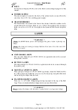
Page 53: ...Are located on the two speakers pods are located to the front of the cabinet inside the Ball receiving trough Access is through the ticket and coin doors SOLO START BUTTON The Solo Start button is th...

Page 54: ...INLET The power inlet is located at the rear of the machine on the Left hand side as viewed from the rear It is a standard IEC inlet socket MAINS SWITCH The mains switch is located on the power inlet...

Page 55: ...e coin door BUTTON LAMPS The button lamps are 12V AC GE194 or equivalent and can be accessed through the speaker pods MATCH 3 POINT LAMPS These groups of lamps are 12V AC GE89 type lamps found the Mat...

Page 56: ...Check and tighten all fixing hardware and fasteners as required Regularly check that all the Display and Button Lamps are operating through the Sounds Lamps and Display Test Replace any globes that a...

Page 57: ...nybody using SECTION B for repairing or modifying any of the components of the game should be a qualified technician having at least a basic knowledge of digital components integrated circuits and ele...

Page 58: ...ge See Diagram Below TRANSFORMER CONNECTORS Locate the machine transformer s in the base of the cabinet If unsure of the location of the transformer s refer to Parts location diagram of this manual Ch...

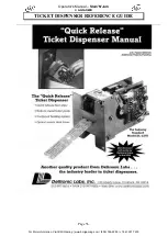
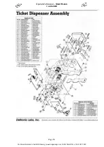
Page 59: ...Operator s Manual Slam N Jam LAI GAMES Page 56 TICKET DISPENSER REFERENCE GUIDE For More Information Visit BMI Gaming www bmigaming com 800 746 2255 1 561 391 7200...

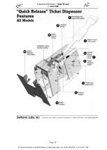
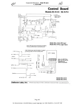
Page 60: ...Operator s Manual Slam N Jam LAI GAMES Page 57 For More Information Visit BMI Gaming www bmigaming com 800 746 2255 1 561 391 7200...

Page 61: ...Operator s Manual Slam N Jam LAI GAMES Page 58 For More Information Visit BMI Gaming www bmigaming com 800 746 2255 1 561 391 7200...

Page 62: ...Operator s Manual Slam N Jam LAI GAMES Page 59 For More Information Visit BMI Gaming www bmigaming com 800 746 2255 1 561 391 7200...

Page 63: ...Operator s Manual Slam N Jam LAI GAMES Page 60 For More Information Visit BMI Gaming www bmigaming com 800 746 2255 1 561 391 7200...

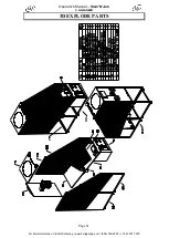
Page 64: ...Operator s Manual Slam N Jam LAI GAMES Page 61 3D EXPLODE PARTS For More Information Visit BMI Gaming www bmigaming com 800 746 2255 1 561 391 7200...

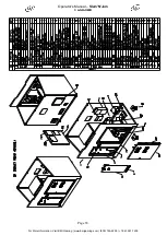
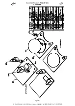
Page 65: ...Operator s Manual Slam N Jam LAI GAMES Page 62 For More Information Visit BMI Gaming www bmigaming com 800 746 2255 1 561 391 7200...

Page 66: ...Operator s Manual Slam N Jam LAI GAMES Page 63 For More Information Visit BMI Gaming www bmigaming com 800 746 2255 1 561 391 7200...

Page 67: ...Operator s Manual Slam N Jam LAI GAMES Page 64 For More Information Visit BMI Gaming www bmigaming com 800 746 2255 1 561 391 7200...

Page 68: ...Operator s Manual Slam N Jam LAI GAMES Page 65 For More Information Visit BMI Gaming www bmigaming com 800 746 2255 1 561 391 7200...

Page 69: ...Operator s Manual Slam N Jam LAI GAMES Page 66 For More Information Visit BMI Gaming www bmigaming com 800 746 2255 1 561 391 7200...

Page 70: ...Operator s Manual Slam N Jam LAI GAMES Page 67 Slam N Jam MAIN WIRING DIAGRAM For More Information Visit BMI Gaming www bmigaming com 800 746 2255 1 561 391 7200...

Page 71: ...ons of the country state and or municipality in which the hardware and licensed software are used or operated b Assembling or causing the assembly of the hardware in a manner not authorized by or disc...

Page 72: ...rchased LAI GAMES shall have no obligation to make repairs necessitated by negligence or interference to any component by any unauthorized personal This will automatically void any existing warranty I...

Reviews: