


12
I
NSTALLING
A
BRASIVE
W
RAPS
Note: When using Pre-Marked™
OR
Pre-Cut™
abrasive wraps, not all of the steps below are
necessary.
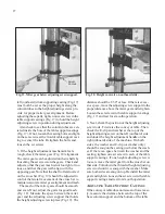
Proper attachment of the abrasive wrap to the
drum is critical to achieving top performance from
the drum sander. Abrasive wraps do not have to
be pre-measured. The end of the roll is first
tapered and attached to the left (out- board) side
of the drum. Then the wrap is wrapped around the
drum, and the second taper is made for
attachment to the right (inboard) side of the
drum. To attach a wrap to the drum, follow the
procedure below.
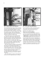
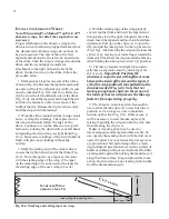
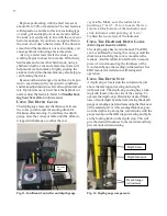
1.
Mark and cut a taper at one end of the roll as
shown in Fig. 10a. Because the tapered end should
use most of the left (outboard) slot width, its end
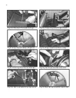
must be trimmed (Fig. 10-b and 10-c). Raise the
clip lever on the left (outboard) side of the drum
(Fig. 10-d). Insert the tapered end through the slot
and into the fastener so that it uses most of the
width of the slot. Release the clip lever to securely
hold the strip end in the fastener.
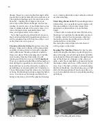
2.
Wrap the strip around the drum, being careful
not to overlap the windings. The tapered cut of
the wrap end should follow the edge of the
drum. Continue to wrap the abrasive in a spiral
fashion by rotating the drum with your left hand
and guiding the strip with your right hand (Fig
10-e). Successive windings of the strip should be
flush with previous windings without any
overlap.
3.
Mark the trailing end of the wrap where it
crosses the right (inboard) end of the drum (Fig.
10-f). From this point, cut a taper as was done
with the starting edge of the wrap. (The taper
on the remaining roll can be used as the taper for
the starting edge of the next wrap to be cut.)
4.
With the trailing edge of the wrap properly
cut, rewrap the drum and insert the tapered end
through the slot in the right (inboard) end of the
drum. Insert the tapered end into the inboard take-
up fastener. Pull up on the clip lever to open the
clip, and pull the take-up lever to the top as shown
(Fig. 10-g). After inserting the wrap end, release the
clip lever by moving your index finger toward the
drum slot. This allows the clip to retain the abrasive
while holding the take-up lever in an “up” position.
5.
The take-up fastener is designed to automati-
cally take up any slack caused by stretching of the
abrasive wrap.
Important: Position the
abrasive wrap in the slot with sufficient room
between the inside of the slot and the tapered
end of the wrap to allow it to be pulled into the
drum as needed (Fig. 10-h). Note that not
leaving enough space between the wrap and
the inside of the slot will prevent the take-up
fastener from operating properly.
6.
The abrasive wrap may stretch enough in
use to allow the take-up lever to reach its lowest
position so it no longer is able to maintain
tension on the strip (Fig. 10-i). If this occurs, it
will be necessary to reset the take-up lever by
raising it, pushing the strip end into the slot, and
then releasing the clip lever.
Note:
A cleaning stick may be used to
remove deposits and help extend abrasive life. To
use, operate the sanding drum with the dust cover
open. (Caution: For your own safety, always wear
eye protection while performing abrasive clean-
ing, and take all precautions to avoid any contact of
hands or clothing with uncovered drums.) Hold the
cleaning stick against the rotating drum and move it
along the drum surface. It is good procedure to use
a shop brush to remove any cleaning stick crumbs
from the drums and conveyor.
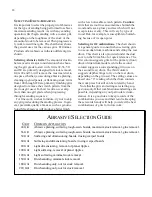
Fig. 10-a. Marking and cutting taper on wrap.
S
ANDPAPER
W
RA
P
(A
BRASIVE
S
IDE
U
P
)
Approx.
3"
Also see Fig. 10-b and Fig. 10-c.
3
"
Summary of Contents for SuperMax 25x2
Page 1: ...OWNERS S MANUAL 25x2 SuperMax Drum Sander LagunaTools com...
Page 36: ...36 STAND ASSEMBLY...
Page 39: ...39 DUAL DRUM HEAD ASSEMBLY...
Page 43: ...43 CONVEYOR MOTOR...
Page 45: ...45 CS DE S CURIT...


