Mainteance
55
ADJUSTING TENSION ROLLERS:
With the sanding drums properly aligned, raise the table to the bottom of the sanding drums. Loosen all four
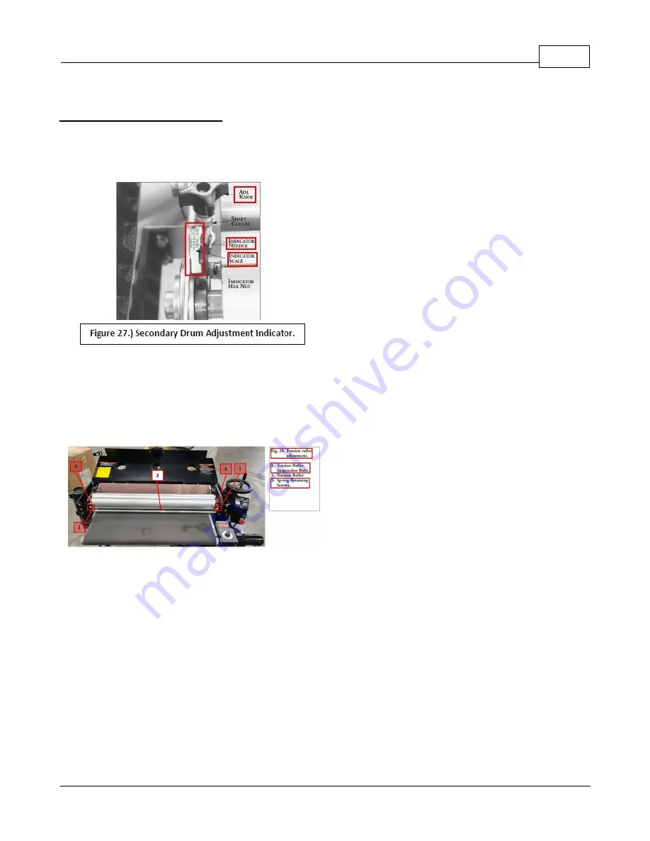
tension roller suspension bolts
(See Item #1 of Figure #28)
. Lower the table by one full turn of the height
adjustment handle. At this position, the tension roller assembly should be resting on the table with the drums
suspended slightly above the table. Then retighten the tension roller suspension bolts.
Note:
Too much tension roller pressure can cause snipe marks which are identified as a visible line running across
the width of the board approximately 2 1/4" from the end of the board. If a snipe mark occurs on the trailing end of
the board, adjust the infeed tension roller. Tension roller pressure can be adjusted two ways, either by loosening
the tension roller spring retaining screws
(See Item #3 of Figure 28)
or by raising the height of the tension rollers.
To adjust the tension rollers to eliminate snipe marks, use this 2-Two Step procedure:
Step 1.)
With the sanding drums properly aligned, loosen all four tension roller suspension bolts. Raise the table to
the bottom of the sanding drum(s). The tension rollers should be resting firmly on the conveyor bed. Tighten only
the two rear (outfeed) tension roller suspension bolts.
Step 2.)
Lower the conveyor table by one full turn of the height adjustment handle. At this point, press down on the
front (infeed) tension roller so it is resting on the table. Now tighten the front (infeed) tension roller suspension bolts.
If there still is a snipe mark left on pieces being sanded, repeat Step 1 and Step 2, but in Step 2 lower the conveyor
bed a half turn instead of a full turn.
Warning:
Improperly adjusted tension rollers (i.e., those set too high, rendering them non-functional) could allow
kick-back/slippage of pieces being sanded.
Summary of Contents for 37 x 2
Page 2: ......
Page 17: ...General Information 17 Castings...
Page 18: ...Double Drum Sander 37 x 2 18 Supermax Specifications...
Page 19: ...General Information 19 Supermax Accessory Supply Check List...
Page 47: ...Mainteance 47...
Page 54: ...Double Drum Sander 37 x 2 54...
Page 56: ...Double Drum Sander 37 x 2 56 Drumhead Assembly Exploded View...
Page 57: ...Drumhead Parts List 57 Drumhead Parts List...
Page 58: ...Double Drum Sander 37 x 2 58...
Page 59: ...Conveyor Exploded View 59 Conveyor Exploded View...
Page 60: ...Double Drum Sander 37 x 2 60 Conveyor Parts List...
Page 61: ...Conveyor Parts List 61...
Page 62: ...Double Drum Sander 37 x 2 62 Exploded Diagrams...
Page 63: ...Parts Lists 63 Parts Lists...
Page 77: ...Disassembly Procedure 77...
Page 79: ...Warranties 79 Warranties Laguna Tools Warranty...
Page 80: ...Double Drum Sander 37 x 2 80 Modifications RMA Policy Laguna Tools Packaging RMA Procedure...
Page 81: ...Warranties 81...


