background image


LAGUNATOOLS.COM 


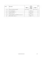
38 


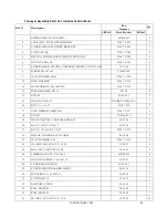
Ref. # 


Description 

Part 

Number 

Qty. 

SB24x2 

Both 

Models 

SB36x2 

57-10 

DC GEAR MOTOR, 180VDC 

93267-2-410 


93367-2-410 

57-12 

FLAT WASHER, M6 


635DS-343 


57-13 

LOCK WASHER, M6 


93267-2-414 


57-14 

HEX NUT, M6x1.0 


635DS-344 


57-15 

SOCKET HEPAD CAP SCREW, 1/4-20x1-1/2 


93267-2-416 


58 

SET SCREW, 1/4-20x1/4 


480BS-113 


Summary of Contents for SuperMax SuperBrush 24 x 2

Page 1: ...OWNERS S MANUAL SuperBrush 24 x 2 SuperBrush 36 x 2 Lagunatools com...

Page 2: ...laint An RMA return merchandise authorization must be requested from Laguna Tools and included with any and all parts or machines returned to Laguna Tools for warranty consideration Any machines retur...

Page 3: ...ety 05 Important Safety Instructions 08 General Safety Rules 11 Assembly 15 Components 20 Power Supply 21 Connecting Power 22 Wiring Diagrams 24 Operation 26 Maintenance 30 Trouble Shooting 31 Explode...

Page 4: ...securing the machine to the pallet 5 Confirm all parts are present and in good condition Figure 1 Inventory NOTE Electrical cord and plug are not included INVENTORY DESCRIPTION QUANTITY A Box 4 Caster...

Page 5: ...which it was designed 8 USE RIGHT TOOL Don t force tool or attachment to do a job for which it was not designed 9 USE PROPER EXTENSION CORD Make sure your extension cord is in good condition When usi...

Page 6: ...ACCESSORIES Consult the owner s manual for recommended accessories The use of improper accessories may cause risk of injury to persons 18 NEVER STAND ON TOOL Serious injury could occur if the tool is...

Page 7: ...on which if not avoided may result in property damage Woodworking metalworking composites etc and similar materials can be dangerous if safe and proper operating procedures are not followed As with al...

Page 8: ...sed as a toy Close attention is necessary when used by or near children 4 Use only as described in this manual Use only manufacturer s recommended attachments 5 Do not use with damaged cord or plug If...

Page 9: ...emove tie rings watches and other jewelry and roll sleeves up past the elbows Remove all loose clothing and confine long hair Non slip footwear or anti skid floor strips are recommended 7 Wear ear pro...

Page 10: ...r part that is damaged should be carefully checked to determine that it will operate properly and perform its intended function Check for alignment of moving parts binding of moving parts breakage of...

Page 11: ...operate or run the machine without closing the drum up against the lid Failure to do so will result in the machine amperage increasing and may trip your circuit Familiarize yourself with the followin...

Page 12: ...ciated with each work piece material and always wear a NIOSH approved respirator to reduce your risk Dust allergies Dust from certain woods and other materials may cause an allergic reaction in people...

Page 13: ...nd use them to instruct others Please read and save these instructions Read carefully before attempting to assemble install operate or maintain the product described Protect yourself and others by obs...

Page 14: ...pes is the equipment grounding wire If repair or replacement of the power cord or plug is necessary do not connect the equipment grounding wire to a live current carrying terminal Check with a qualifi...

Page 15: ...h 1 2 wrench 5mm hex wrench Power Cord and Plug unless hard wiring into a disconnect To assemble your SuperBrush follow these steps For your own safety do not connect the machine to the power source u...

Page 16: ...Table Support Set Screws Caution Label 2 Attach the four casters to the legs of the machine by inserting the stud into the bottom hole and attaching a washer and nut Figure 4 Attaching casters 3 Lowe...

Page 17: ...and tighten the nut Note these set screws are brass tipped and are designed to lightly rub on the column Figure 5 Table Support Set Screws NOTE There are four motor support screws pre set at the facto...

Page 18: ...he brush heads Figure 7A B Shipping Arbor and Bearings 7 Installing brush heads same process for both brush heads A Install brush heads if not already installed by removing brush head from shipping bo...

Page 19: ...tension of the drive belt Proper tension is slight deflection of the drive belt when pressed from the side K Make sure all bolts and set screws are tight 8 Check alignment parallelism of the brush hea...

Page 20: ...and material Assembly continued in Power Supply Figure 9 Dust Ports SB 24 x 2 shown COMPONENTS Figure 10 Main Components of SuperBrush 36 x 2 similar to SB 24 x 2 Four 4 dust ports SB24 x 2 Six 4 dust...

Page 21: ...d electrician Circuit Size 208 230V 3 Phase 50 Amp minimum IN ALL CASES MAKE CERTAIN THE RECEPTACLE IN QUESTION IS PROPERLY GROUNDED IF YOU ARE NOT SURE HAVE A QUALIFIED ELECTRICIAN CHECK THE RECEPTAC...

Page 22: ...rding to local codes A qualified electrician should do the connection When completed the machine must conform to the National Electric Code and all local codes and ordinances FUNCTION Control Panel Fr...

Page 23: ...ure 13 Control Panel Components Back NOTE The speed of High Speed Conveyor lifting can be adjusted on the back of the control panel with a rotating stud Conveyor High Speed Adjustment RPM Adjustment 2...

Page 24: ...er Connections Wiring FWD REV SWITCH V RED BLACK GREEN WHITE T S R W U FRONT ON OFF SWITCH FRONT MOTOR RED BLACK WHITE GREEN REAR ON OFF SWITCH FWD REV SWITCH BACK MOTOR V BLACK RED RED BLACK WHITE GR...

Page 25: ...LAGUNATOOLS COM 25 INTERNAL WIRING Figure 15 Internal Wiring...

Page 26: ...brush head onto material to be processed by either turning the height adjustment handle 1 revolution equals 3 32 or by pressing the UP DOWN switch on the control panel NOTE brush contact will vary wi...

Page 27: ...is to read the bristle penetration into stock being processed A With machine OFF place stock under the brush head B Adjust conveyor table up or down until the tip of the longest bristles are just abou...

Page 28: ...material If not correct press OFF button wait for machine to stop Change rotation with rotation switch with Front Brush Turn ON brush 8 Staring Conveyor A To start conveyor press CONVEYOR ON button F...

Page 29: ...10 While the brush is running rotate the handle above each motor to adjust RPM Confirm correct RPM setting with sample testing information or your salesperson RPM reads out on yellow indicator near mo...

Page 30: ...positively disconnected to the machine for maintenance or repairs MAINTENANCE Conveyor Belt Keep conveyor belt centered on conveyor bed Adjust tracking stud as needed Keep conveyor belt clean to help...

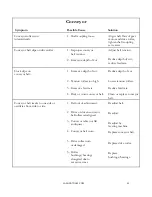
Page 31: ...cause Replacefuse Brush motor overloads 1 Inadequate circuit 2 Machine overloaded Check electrical requirements Use slower feed rate slower brushRPM reduce depth of cut Conveyor motor oscillates 1 Mot...

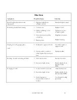
Page 32: ...depth of cut Reduce depth of cut 2 Tension rollers too high Lower tension rollers 3 Excessive feed rate Reduce feed rate 4 Dirty or worn conveyor belt Clean or replace conveyor belt Conveyor belt tra...

Page 33: ...set screws Replace bearing Sniping of stock gouging near 1 Inadequate support of stock Use roller stands to support stock end 2 Conveyor drive or driven Readjust rollers rollers higher than conveyor...

Page 34: ...LAGUNATOOLS COM 34 Exploded Views STAND ASSEMBLY 1of 2 Figure 22 Stand Assembly...

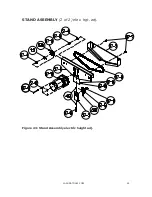
Page 35: ...LAGUNATOOLS COM 35 STAND ASSEMBLY 2 of 2 elec hgt adj Figure 23 Stand Assembly electric height adj...

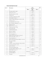
Page 36: ...AFT COLLAR 1 2 I D 20 1103 6 13 TUBE COLUMN 30 3044 4 14 SCREW RPM MOTOR 30 1209 2 15 MOUNT MOTOR 30 5103 2 16 HEX NUT 5 16 18 12 0003 12 17 FLAT WASHER 5 16 11 0206 12 18 BRASS TIPPED SET SCREW 5 16...

Page 37: ...46 SPACER STAND LEG TIE 30 1045 2 47 SET SCREW 1 4 20x1 BRASS TIPPED 93267 2 147 2 48 FLAT WASHER 1 4 480BS 145 4 49 HEX NUT 1 4 20 12 0001 4 50 LOCK WASHER 3 8 480BS 111 48 51 BRACKET TABLE MOUNT 40...

Page 38: ...h Models SB36x2 57 10 DC GEAR MOTOR 180VDC 93267 2 410 93367 2 410 1 57 12 FLAT WASHER M6 635DS 343 4 57 13 LOCK WASHER M6 93267 2 414 4 57 14 HEX NUT M6x1 0 635DS 344 4 57 15 SOCKET HEPAD CAP SCREW 1...

Page 39: ...LAGUNATOOLS COM 39 HEAD ASSEMBLY Front 1 2 Figure 24 Head Assembly Front 1 2 without brush...

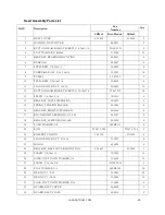
Page 40: ...6 13 SCREW 1 4 20x1 3 4 10 3213 8 14 BRACKET LEFT SUSPENSION 40 0323 4 15 SPRING TENSION ROLLER 20 3284 8 16 BRACKET RIGHT SUSPENSION 40 0326 4 17 ROUND OILITE BUSHING 1 2 I D 50 3107 8 18 BRACKET SUS...

Page 41: ...0 SPACER HEAD 30 1310 2 41 KNOB LOCKING W SET SCREW 81 3132W 2 42 SUPPORT ADJUSTING SCREW 30 1112 2 43A DEPTH GAUGE ROD 30 1260HR 1 43B DECAL SCALE 94 1654 1 44 SOCKET HEAD CAP SCREW 3 8 16x4 1 2 10 9...

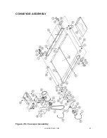
Page 42: ...LAGUNATOOLS COM 42 CONVEYOR ASSEMBLY Figure 25 Conveyor Assembly...

Page 43: ...LAGUNATOOLS COM 43 CONTROL PANEL ASSEMBLY Incl w Conveyor Parts Figure 26 Control Panel Assembly Included with Conveyor parts list...

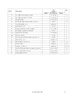
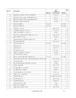
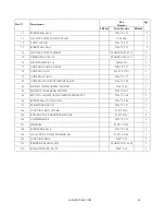
Page 44: ...STRAIN RELIEF PG 19 PG 19 4 14 V BELT 50 2029 1 2 15 HEX NUT M4x0 7 PLAREVO1836 1153 7 16 KEY x x 4 91267 352 2 17 ZINC OXIDE VARISTOR 93267 2 317 1 18 KNOB 72 6106 01A 1 19 PULLEY DRIVE VARIABLE SPEE...

Page 45: ...FWD REV SWITCH 93267 2 348 2 49 CONVEYOR BED 40 4101 40 4201 2 50 E RING E 12 93267 2 350 2 51 E RING E 15 20 0753 2 52 STARKLOCK 5 8 BV 6185 1 53 HEX CAP SCREW 3 8 16x3 4 10 9205 2 54 FLAT WASHER 3 8...

Page 46: ...L PANEL 93267 2 379 1 80 CONTROL BOX SUPPORT BRACKET 93267 2 380 1 82 MOTOR CORD FRONT MOTOR 93267 330 1 84 MOTOR CORD REAR MOTOR 93267 330 1 1 85 BUTTON HEAD SOCKET SCREW M5X0 8X12 93267 2 385 1 86 S...

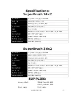
Page 47: ...0 x 1530 mm Machine weight 883 lbs 401 kg Shipping weight 1342 lbs 610 kg SuperBrush 36x2 Main Motor 7 1 2 HP each 2 1750 RPM Electrical 208V 230V 60Hz 3PH Circuit 50 Amp min at 208V 3PH Air Volume 60...

Page 48: ...PM SERIAL NO Taiwan TCP SUPERBRUSH 36x2 STOCK NO 93367 2 POWER 230V 3Ph 40 8A 60Hz 650 1350 RPM SERIAL NO Taiwan TCP Contact Laguna Tools for supplies 800 234 1976 www lagunatools com LAGUNA TOOLS 744...

Reviews: