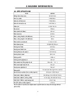

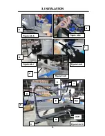

3. INSTALLATION
17
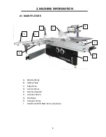
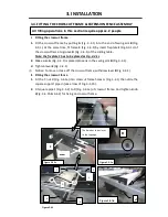
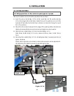
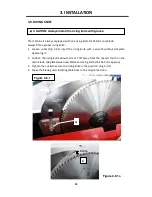
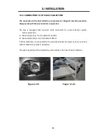
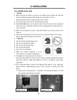
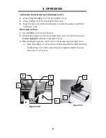
3-7. FITTING RIP FENCE
Remove the washer and nut from the round bar first and then
1.
Insert the screw rods
H
(Fig. 3-7.1a) of the round bar into the position
A
(Fig.
3-7.1) of working table and extension table then put the washers and nut at the
back side of the table, then fasten them in (there are 4 points for fixing the round
bar in this position).
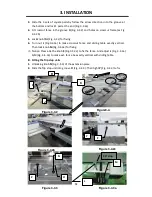
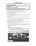
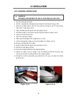
2.
Mount the fence scale (ruler) set to the edge of the working table and extension
table by fastening the fence scale (ruler) set with washer and lock washer
3.
Slide rip fence support
C
(Fig. 3-7.1)into round bar
D
(Fig. 3-7.1)
Note: Move handle
E
(Fig. 3-7.1) up to release rip fence, down to lock the rip
fence.
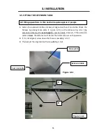
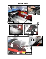
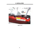
4.
Mounting fence plate
F
(Fig. 3-7.1) to clamping assembly in upward position and
tighten handle
G
.
Notice: Before operation, the 0 mark on the rip fence scale must be aligned with
the right side of the blade to ensure the processing accurate.
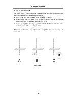
All fitting operations in this section require approx. 2 people
Figure 3-7.1a
F
G
C
D
E
A
B
Figure 3-7.1
H
Summary of Contents for P12 10
Page 26: ...3 INSTALLATION 22 Figure 3 10 2 D C ...
Page 52: ......
Page 53: ......
Page 54: ...MPSP12 10 0135 ASSEM 1 1 23 1 ...
Page 58: ...MPSP12 10 0135 ASSEM 1 2 4 5 ...
Page 60: ...MPSP12 10 0135 ASSEM 3 1 5 7 ...
Page 63: ...MPSP12 10 0135 ASSEM 3 2 6 10 ...
Page 65: ...MPSP12 10 0135 ASSEM 3 3 5 12 ...
Page 67: ...MPSP12 10 0135 ASSEM 4 10 14 ...
Page 69: ...MPSP12 10 0135 ASSEM 5 7 16 ...
Page 72: ...MPSP12 10 0135 ASSEM 6 1 19 ...
Page 74: ...MPSP12 10 0135 ASSEM 6 2 21 ...
Page 76: ...MPSP12 10 0135 ASSEM 6 3 23 ...
Page 78: ...MPSP12 10 0135 ASSEM 7 6 3200mm 25 ...
Page 80: ...MPSP12 10 0135 ASSEM 8 1 27 ...
Page 82: ...MPSP12 10 0135 ASSEM 9 3 29 ...
Page 85: ...MPSP12 10 0135 ASSEM 10 3 32 ...
Page 89: ...MPSP12 10 0135 ASSEM 12 6 4 36 ...
Page 92: ...MPSP12 10 0135 ASSEM 12 10 39 ...