background image

LaCie USB 2.0 / FireWire 400 & 800 PCI Card • 

DESIGN BY SISMO


Installing Your PCI Card

User Manual 

page 8

3.2.  Inserting Your LaCie PCI Card

Required Tools


Philips-head and/or flat-head screw driver


Computer System Manual

1.   Turn off your computer and disconnect all external periph-

eral devices and cables, i.e. power cord, modem/fax line, 
monitor, etc. 

2.  Remove your computer’s cover. For most computers, several 

screws will need to be unseated before you can remove the 
computer’s cover. These screws are usually located at the 
rear of the computer, along the edge of the cover. However, 
placement of these screws and cover attachment may vary by 
manufacturer, so please refer to your computer’s manual for 
specific details.

3.  Once you have removed the cover, you will need to locate 

the PCI slots on the motherboard. The PCI slots are generally 
located in the back of the computer, with the slots built into 
the side-wall of the computer (please refer to your computer 
system’s manual for the exact location of your PCI slots – the 
LaCie PCI Card may be installed in either a 32 or 64-bit PCI 
card slot). If necessary, you may need to remove the expan-
sion slot cover, and you may also need to remove any add-in 
boards which block access to the PCI slots. 

4.  Take the LaCie PCI Card out of its anti-static blister package 

and, being careful to touch only the anti-static gripping pad,  
push the card into the empty PCI card slot. There is only way 
to mount the card, so if you are having problems inserting 
the card into the PCI slot, make sure that it is oriented cor-
rectly. Be sure that the gold contact pins of the PCI card are 
seated completely inside your computer’s PCI slot. Be aware 
that it may take some force to get the card fully seated in 
the slot.

5.  Once the PCI card is seated correctly, tighten with a screw.

6.  If necessary, replace any add-in boards that you removed 

in Step 3.

7.   Now you are ready to put the computer’s cover back on 

and reconnect all of your external peripheral devices and 
cables.

8.   Power on your computer. After the start up procedure has 

finished, you should be able to connect devices through the 
available FireWire ports.
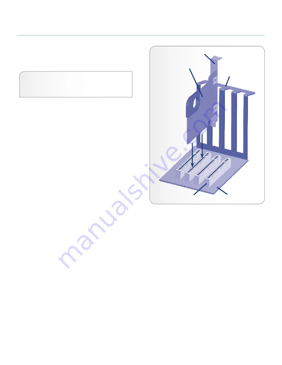
LaCie PCI Card

System frame

Motherboard

PCI or PCI-X slot

Bracket

Summary of Contents for 130822 - FireWire 400 ANF 800 USB 2.0 PCI Card...

Page 1: ...5 1 1 Minimum System Requirements 5 2 1 Package Content 6 2 2 View of the Card 6 3 Installing Your LaCie PCI Card 7 3 1 Electrostatic Discharge ESD 7 3 2 Inserting Your LaCie PCI Card 8 3 3 Driver In...

Page 2: ...erates uses and can radiate radio frequency en ergy and if not installed and used in ac cordance with the instruction manual may cause harmful interference to radio com munications Operation of this e...

Page 3: ...ng your card in an en vironment that is too cold or humid may damage the unit IMPORTANT INFO Any loss corrup tion or destruction of data while using a LaCie drive is the sole responsibility of the use...

Page 4: ...he quick easy and affordable way to expand connectivity to nearly all of your peripherals accessing several at once This LaCie PCI Card is plug play so just plug it in and it s ready to work for you O...

Page 5: ...0 FireWire 400 800 PCI Card ensure that you have properly grounded yourself Electrostatic Discharge ESD can quickly and easily damage or destroy your component or your computer Please see section 3 1...

Page 6: ...This port is where you attach the FireWire 800 interface cables 3 One FireWire 400 Port This port is where you attach the FireWire 400 interface cables 2 1 Package Content 1 LaCie USB 2 0 FireWire 400...

Page 7: ...harge or ESD ESD can cause two different types of damage to computers and peripherals 1 Catastrophic which is the complete loss of de vice functionality and 2 Latent Defect where the device is only pa...

Page 8: ...our PCI slots the LaCie PCI Card may be installed in either a 32 or 64 bit PCI card slot If necessary you may need to remove the expan sion slot cover and you may also need to remove any add in boards...

Page 9: ...nstallation Windows Users There are no drivers to install for Windows 2000 2003 Server XP and Vista The LaCie FireWire PCI Card has the drivers built into the BIOS for these operating systems Mac User...

Page 10: ...peed USB 2 0 Bus Unfortunately no USB devices will still operate at 12Mb s at full speed and 1 5Mb s at low speed on a Hi Speed USB 2 0 bus Even though USB 1 0 devices won t run any faster they can wo...

Page 11: ...ude the support of increased ca bling distances and a newly enhanced arbitration architecture Utilizing cables constructed of professional grade glass optical fiber when both devices are connected via...

Page 12: ...FireWire 800 devices to work they must be connected by placing the 9 pin end of the FireWire cable into the FireWire 800 port of the device and the opposite 6 pin or 4 pin end into the FireWire 400 p...

Page 13: ...work properly con tact us via the provided Web link Before contacting us make sure that you are in front of your computer and that you have the following information on hand Your card s serial number...

Page 14: ...t http www lacie com fr contact LaCie Germany Contact us at http www lacie com de contact LaCie Italy Contact us at http www lacie com it contact LaCie Japan Contact us at http www lacie com jp contac...

Page 15: ...electrical fault improper packaging or accident The card was installed improperly The serial number of the card is defaced or missing LaCie will not under any circumstances be liable for direct spe ci...

Reviews: