background image

                                                                                                                        H50/150 Smart – User Manual 


SPECIFICATION 

Model 

Smart 

H150-1000N 

Smart 

H150-1000NLT 

Smart 

H150-1500NS 

Smart 

H150-2100NS 

Smart 

H150-2100NSLT 

Smart 

H150-3000NS 

Temp. control range   

35 


-20~35


35 


35 


-20~35


35 


Temp. control mode 

PID 

Cooling mode 

Compressor cooling 

Refrigerant 

R134A 

Temp. stability 

±0.1 


Cooling capacity 

1000W@25


1000W@25


100W @-15


1500W@25


2100W@25


2100W@25


200W @-15


3000W@25


Pump capacity 

5L /min 

5L /min 

5L /min 

13L /min 

13L /min 

13L /min 

Reservoir volume 

2.2L 

2.2L 

3.5L 

3.5L 

3.5L 

3.5L 

Recirculating pump 

PR4 

PR4 

PR4 

PRG8 

PRG8 

PRG8 

Weight 

56Kg 

56Kg 

72Kg 

80Kg 

80Kg 

85Kg 

Dimension(LxWxHmm) 

560x360x590 

650x385x625 

740x460x700 

NOTE: the value of temperature stability is tested in standard operating mode. 


Model 

H150-5000N 

H150-7000N 

H150-9000N 

Temp. control range 

35 


Temp. control mode 

PID 

Cooling mode 

Compressor cooling 

Refrigerant 

R404A 

Temp. stability 

±0.2 


Cooling capacity 

5000W@25


7000W@25


9000W@25


Pump capacity 

13L /min 

13L /min 

13L /min 

Reservoir volume 

22L 

22L 

22L 

Recirculating pump 

PRG8 

PRG8 

PRG8 

Weight 

170Kg 

170Kg 

170Kg 

Dimension(LxWxHmm) 

690x640x1100 

690x640x1100 

690x640x1100 

Summary of Contents for H50 Series

Page 1: ...H50 150 SMART SERIES WATER CHILLERS USER MANUAL...

Page 2: ...invite you to read carefully this user manual and to keep it close to the instrument for convenient and fast consulting For any possible clarification or any request for assistance please contact eith...

Page 3: ...MBING REQUIREMENTS 14 3 4 FLUIDS 15 4 OPERATION PROCEDURE 16 4 1 LCD CONTROLLER 16 4 2 TOUCH CONTROLLER 17 4 2 1 MAIN INTERFACE 17 4 2 2 MAIN MENU 18 4 2 3 ALARMS 20 4 2 4 START UP SHUT DOWN 22 4 2 5...

Page 4: ...tion contained in this document may be the object of patent applications by LABTECH The possession of this document does not confer any license rights in and to such patents The following names are LA...

Page 5: ...following keys FRONT VIEW The front panel consists of the following parts Actual Temperature Alarm Cooling Indication Working State Indication Setpoint Temperature Value Increase Backlight On Off Val...

Page 6: ...lating pump a reservoir and a microprocessor temperature controller Technical specification Model H50 500 115V H50 500 DF Temp control range 5 35 Temp control mode PID Cooling mode Compressor cooling...

Page 7: ...H50 150 Smart User Manual 7 SMART H150 CONTROL PANEL Touch controller H150 Series FRONT VIEW Temperature Controller Liquid Level Indicator...

Page 8: ...H50 150 Smart User Manual 8 REAR VIEW Liquid Supply Connection Liquid Return Connection Pressure Regulation Valve Liquid Drain Electrical Socket Fuse holder...

Page 9: ...n Reservoir volume 2 2L 2 2L 3 5L 3 5L 3 5L 3 5L Recirculating pump PR4 PR4 PR4 PRG8 PRG8 PRG8 Weight 56Kg 56Kg 72Kg 80Kg 80Kg 85Kg Dimension LxWxHmm 560x360x590 650x385x625 740x460x700 NOTE the value...

Page 10: ...H50 150 Smart User Manual 10 MAGNETIC PRG PR SERIES PUMP CAPACITY...

Page 11: ...circuit parts in order to avoid a short circuit or open circuit Fire safety Numerous reagents are flammable and explosive When the solvent vapor concentration reaches a certain level it would be flam...

Page 12: ...the manufacturer s warranty Transport the unit with care Inclination angle must be less than 60 degrees otherwise the refrigeration system could be damaged Sudden jolts or drops can damage the refrige...

Page 13: ...ront of the unit and discharged through the rear and side panels The unit must be properly positioned so that the intake and discharge are not impeded A minimum clearance of 1 meter nearly 3 feet on a...

Page 14: ...PPLY and RETURN Remove the plastic protective caps from both plumbing connections Install the barbed adapters to these connections Connect the fitting SUPPLY to the hose feeding the inlet of your appl...

Page 15: ...oled as short as possible Tubing should be straight and without bends If diameter reductions must be made they should be made on the inlet and outlet of the instrument to be cooled not on the chiller...

Page 16: ...than the setpoint temperature The refrigeration system will stop automatically Alarm code H A will be displayed and the buzzer alarm sound when the temperature is overshoot and 5 or more higher than t...

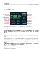
Page 17: ...hem e Running Alarm status shows the unit status between Running and Alarm Available alarms Temperature Over range Liquid Level Gas Pressure Liquid Pressure Flow Rate Self Testing High Temperature Low...

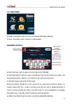
Page 18: ...confirm the new value touch OK button c Parameter Range parameter setting range d Numeric Keypad keypad can only be used when the value area is activated yellow For negative values touch the button in...

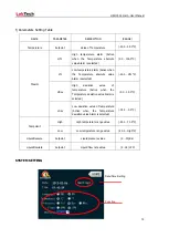
Page 19: ...alue Alarm is selected 20 0 HTL C HDev High deviation value of temperature Active when the Temperature deviation value Alarm is selected 0 0 35 0 C LDev Low deviation value of temperature Active when...

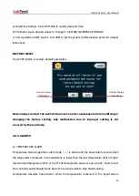
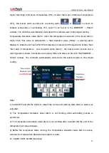
Page 20: ...e factory setting Any malfunction due to improper setting is not covered by the warranty 4 2 3 ALARMS a TEMPERATURE ALARM Temperature Over range Alarm alarm code is shown and the buzzer alarm sounds w...

Page 21: ...e of temperature Low deviation value LDev the buzzer alarm sounds and a warning alarm is shown to indicate over cooling HDev and LDev can be set in the PARAMSET TAlarm window The controller automatica...

Page 22: ...e than 5 seconds When the Water Flow Rate Analogy Amount alarm is activated the touch controller shows flow rate abnormal alarm and the buzzer sounds if the flow sensor detects a flow rate higher than...

Page 23: ...the circular regulation valve opening on the rear of the unit Turn the threaded stem fully counterclockwise If the unit is not connected to the instrument to be cooled install a loop of hose equipped...

Page 24: ...he cup and disconnect the fitting on the chiller Before positioning the unit in the storage be sure the drain tap is closed 5 2 CONDENSER CLEANING For proper operation the unit needs to pull a substan...

Page 25: ...heck the pressure gauge adjust the relief valve as necessary 6 3 INADEQUATE TEMPERATURE CONTROL Verify the setpoint If the temperature continues to rise make sure the instrument to be cooled heat load...

Page 26: ...H50 150 Smart User Manual 26 7 FLOW CHART...

Page 27: ...inators who are ready to quickly assist customers with answers and solutions to service needs and application questions For any possible clarification or any request for assistance please contact eith...

Reviews: