


Hydraulic System Maintenance
89
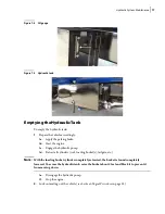
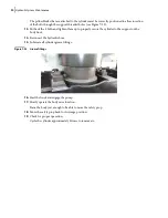
4.
Remove the four bolts from the cylinder cover pillow blocks (see Figure 7
21).
Both pillow blocks will remain in place.
Figure 7
-
21 Cover pillow blocks
5.
Using a lifting device, lift the body just enough to be able to tilt the safety prop under the body.
The cylinder will remain in place.
I
MPORTANT
:
Ensure that the cylinder remains in vertical position while lifting the body.
6.
Install the safety prop.
7.
Lower the body on the safety prop.
8.
Using a lifting device, remove the body hoist cylinder carefully.
Save both pillow blocks for the replacement cylinder (see Figure 7
9.
Place the pillow blocks that were set aside on the pins of the new cylinder.
10.
Using a lifting device, install the new body hoist cylinder on the base support and reinstall both
base pillow blocks (see Figure 7
20).
11.
Put back all 4 bolts and tighten them up to hold both base pillow blocks in place (see Figure
20).
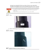
12.
Using a lifting device, extend the cylinder in order to fix it properly to the body.
Figure 7
-
22 Securing cylinder to support
Summary of Contents for Top Select
Page 1: ...TOP SELECT TM MAINTENANCE MANUAL...
Page 2: ......
Page 3: ...TOP SELECT MAINTENANCE MANUAL...
Page 8: ...vi Table of Contents...
Page 34: ...26 Safety...
Page 40: ...32 General Cleanliness...
Page 72: ...64 Loading Container Maintenance...
Page 104: ...96 Preventive Maintenance...
Page 121: ...Lubrication 113 Figure 11 2 Body hinges Grease Fittings on Body Figure 11 3 Tailgate and hooks...
Page 122: ...114 Lubrication Figure 11 4 Partition Figure 11 5 Optional Maximizer Location of lube zerks...
Page 123: ...Lubrication 115 Figure 11 6 Roof hinges and loading cylinders...
Page 124: ...116 Lubrication Figure 11 7 Lube chart...
Page 132: ...124 Troubleshooting...
Page 134: ...126 Hydraulic and Pneumatic Circuit Diagrams Hydraulic Schematics Single Side Bucket...
Page 135: ...Hydraulic and Pneumatic Circuit Diagrams 127 Single Side Bucket w Maximizer...
Page 136: ...128 Hydraulic and Pneumatic Circuit Diagrams Dual Side Bucket...
Page 137: ...Hydraulic and Pneumatic Circuit Diagrams 129 Dual Side Bucket w Maximizer...
Page 139: ...Hydraulic and Pneumatic Circuit Diagrams 131 Air System Schematics TS 1000 w Options...
Page 140: ...132 Hydraulic and Pneumatic Circuit Diagrams TS 2000 w Options...