


82
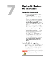
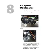
Hydraulic System Maintenance
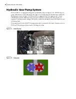
Hydraulic Gear Pump System
The T
OP
S
ELECT
™ is equipped with a gear type hydraulic pump (see Figure 7
12). With this type of
pump, all functions on the truck require the engine to run at idle except for the body hoist and for the
Maximizer system (see Figure 7
13) if the unit is so equipped. In fact, the engine needs to run at
1500 RPM to make the Maximizer move rearwards/forwards and to make the body hoist move
upwards. The main pressure setting is 2000 psi for a unit with a standard body and 2300 psi for a unit
with a long body.
The pump is part of a hot-shift PTO/pump system and is connected to the truck’s transmission via a
PTO unit. The pump provides automatic clutching at any time.
Figure 7
-
11 Hot-shift pump
Figure 7
-
12 Gear pump
Pump
PTO
Transmission
Summary of Contents for Top Select
Page 1: ...TOP SELECT TM MAINTENANCE MANUAL...
Page 2: ......
Page 3: ...TOP SELECT MAINTENANCE MANUAL...
Page 8: ...vi Table of Contents...
Page 34: ...26 Safety...
Page 40: ...32 General Cleanliness...
Page 72: ...64 Loading Container Maintenance...
Page 104: ...96 Preventive Maintenance...
Page 121: ...Lubrication 113 Figure 11 2 Body hinges Grease Fittings on Body Figure 11 3 Tailgate and hooks...
Page 122: ...114 Lubrication Figure 11 4 Partition Figure 11 5 Optional Maximizer Location of lube zerks...
Page 123: ...Lubrication 115 Figure 11 6 Roof hinges and loading cylinders...
Page 124: ...116 Lubrication Figure 11 7 Lube chart...
Page 132: ...124 Troubleshooting...
Page 134: ...126 Hydraulic and Pneumatic Circuit Diagrams Hydraulic Schematics Single Side Bucket...
Page 135: ...Hydraulic and Pneumatic Circuit Diagrams 127 Single Side Bucket w Maximizer...
Page 136: ...128 Hydraulic and Pneumatic Circuit Diagrams Dual Side Bucket...
Page 137: ...Hydraulic and Pneumatic Circuit Diagrams 129 Dual Side Bucket w Maximizer...
Page 139: ...Hydraulic and Pneumatic Circuit Diagrams 131 Air System Schematics TS 1000 w Options...
Page 140: ...132 Hydraulic and Pneumatic Circuit Diagrams TS 2000 w Options...