


Loading Container Maintenance
49
Adjusting Length of Bucket Rods
The adjustment of the bucket rods is done to correct the bucket unloading angle which must be
between 45° and 50° and the horizontal level of the bucket.
N
OTE
:
The tolerance in the horizontal plane of the bucket is ½ inch.
To adjust the length of the rods:
1.
Set the bucket in parallel position with the body.
N
OTE
:
You can use a pair of jacks, one at one end of the bucket and one at the other end, and use the
horizontal guide on the body as reference (see Figure 5
11).
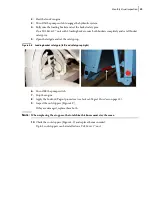
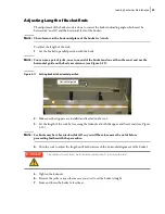
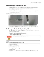
Figure 5
-
11 Setting bucket in horizontal position
2.
Make sure the stoppers are installed and leveled on the roof.
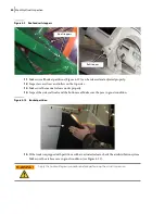
3.
Set the length of the rods by loosening the locknuts at both the upper and lower ends (see Figure
10).
N
OTE
:
Locknuts may have been tack welded. If so, you will have to remove the welds before
proceeding further with the procedure.
4.
Turn the rods to adjust the length until both rods reach the horizontal alignment of the bucket.
5.
Tighten the locknuts.
6.
Remove the jacks or any other means you used to set the bucket straight.
7.
Raise and lower the bucket a few times.
The rod end must always be inserted a minimum of 1 inch into the rod.
Horizontal guide
DANGER!
Summary of Contents for Top Select
Page 1: ...TOP SELECT TM MAINTENANCE MANUAL...
Page 2: ......
Page 3: ...TOP SELECT MAINTENANCE MANUAL...
Page 8: ...vi Table of Contents...
Page 34: ...26 Safety...
Page 40: ...32 General Cleanliness...
Page 72: ...64 Loading Container Maintenance...
Page 104: ...96 Preventive Maintenance...
Page 121: ...Lubrication 113 Figure 11 2 Body hinges Grease Fittings on Body Figure 11 3 Tailgate and hooks...
Page 122: ...114 Lubrication Figure 11 4 Partition Figure 11 5 Optional Maximizer Location of lube zerks...
Page 123: ...Lubrication 115 Figure 11 6 Roof hinges and loading cylinders...
Page 124: ...116 Lubrication Figure 11 7 Lube chart...
Page 132: ...124 Troubleshooting...
Page 134: ...126 Hydraulic and Pneumatic Circuit Diagrams Hydraulic Schematics Single Side Bucket...
Page 135: ...Hydraulic and Pneumatic Circuit Diagrams 127 Single Side Bucket w Maximizer...
Page 136: ...128 Hydraulic and Pneumatic Circuit Diagrams Dual Side Bucket...
Page 137: ...Hydraulic and Pneumatic Circuit Diagrams 129 Dual Side Bucket w Maximizer...
Page 139: ...Hydraulic and Pneumatic Circuit Diagrams 131 Air System Schematics TS 1000 w Options...
Page 140: ...132 Hydraulic and Pneumatic Circuit Diagrams TS 2000 w Options...