Operating the W
ITTKE
R
ETRO
F
L
TM
67
Pressure Relief Valve
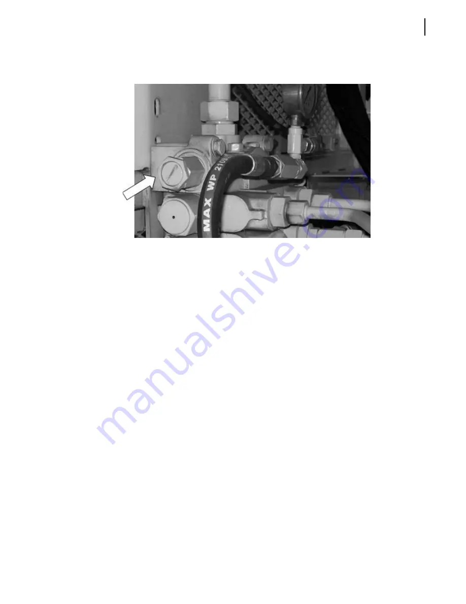
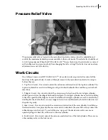
The pressure relief valve is located in the main directional valve inlet section. It is adjustable and
controls the maximum hydraulic pressure available to the work circuits. The relief valve should be set
to 2,300 psi maximum. When the W
ITTKE
R
ETRO
F
L
TM
leaves the factory, the relief valve is covered
with a rubber seal to prevent anybody from changing the valve setting. That valve does not need any
adjustment once out of the factory.
Work Circuits
On a full eject commercial W
ITTKE
R
ETRO
F
L
TM
, five work circuits are provided to control all the
functions of the packer body. In order of their placement in the main directional valve, from top to
bottom they are:
1. Top Door Circuit – this circuit controls the extension and retraction of the top door cylinder. The
top door cylinder has a restrictor fitting in each port to limit hydraulic flow, and thus speed, in both
directions.
2. Tailgate Circuit – this circuit controls the extension and retraction of the two tailgate cylinders
which open and close the tailgate latch and the tailgate. The tailgate cylinders have a restrictor fitting
to limit the speed that the tailgate closes at. In addition, the tailgate cylinders are each controlled by a
double pilot check valve that a) ensures tailgate descent is controlled and b) the latch hook does not
drop due to gravity.
3. Arm Circuit – this circuit controls the extension and retraction of the arm cylinders. In addition, a
deceleration valve is employed in the arm raise circuit to decelerate the arms before they contact the
rubber bumpers on the body. To control the arm ‘up’ speed, the deceleration valve uses a cam
operated plunger to limit the oil flow out of the arm cylinders.
4. Fork Circuit – this circuit controls the extension and retraction of the fork cylinders. There are no
other auxiliary valves in the fork circuit.
Summary of Contents for Pendpac WITTKE RETRO FL
Page 1: ...WITTKE RETRO FLTM OPERATOR MANUAL...
Page 2: ......
Page 3: ...WITTKE RETRO FLTM OPERATOR MANUAL...
Page 5: ......
Page 6: ......
Page 10: ...viii Table of Contents...
Page 17: ...Safety 7 Keep Hands and Body Clear...
Page 18: ...8 Safety Stand Clear of Tailgate Extreme Crush Hazard Service Hoist Handle...
Page 19: ...Safety 9 Do Not Climb on Canopy Check All Bridge Clearances...
Page 21: ...Safety 11 Crush Hazard Body May Fall The Top of This Vehicle is High Enough...
Page 22: ...12 Safety Danger of Electrocution Damage to Vehicle Frame is Heat Treated...
Page 24: ...14 Safety Disconnect All Batteries and Electronic Control Modules Remove Cap Slowly...
Page 25: ...Safety 15 Extension Ladder Must Be Secured Service Hoist Instructions...
Page 27: ...Safety 17 Setting the Tailgate Props Street Side...
Page 29: ...Safety 19 Hydraulic Oil Grade Notice Hydraulic Oil Fill Level...
Page 66: ...56 In Cab Control Console...


