


Hydraulic System
83
Adjusting Hydraulic Pressure
A 0–4000
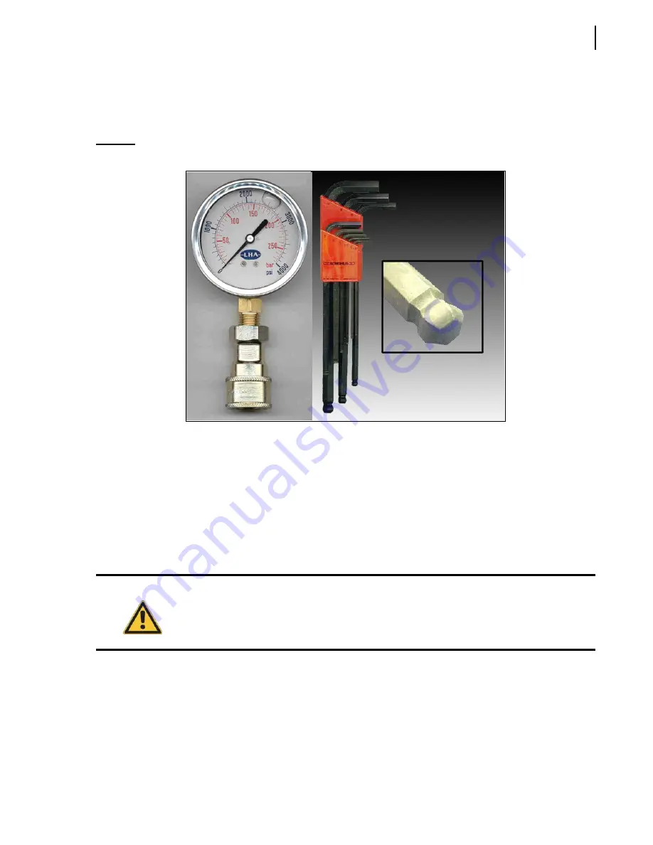
psi pressure gauge as well as a set of ball-end hex keys are required to adjust system pressure
Figure 5-10 Pressure gauge and ball-end hex key
The pressures of the various hydraulic functions of the Minimax are set up at the factory for optimal
performance. However, when you perform maintenance work on the hydraulic system of the truck,
you may need to adjust the hydraulic pressure for a number of reasons. For more information, see
Adjusting Main Pressure on Body Control Valve
M
INIMAX
™vehicles is equipped with an electro-hydraulic body control valve to power body hydraulic
functions, including the tailgate, the packer, and the crusher panel, if installed.
To adjust the pressure:
1.
Start the engine and engage the hydraulic system.
2.
Install a 0–4000
psi pressure gauge on the quick-connect coupler located on the hydraulic valve.
Warning!
Make sure that the ball valve on the suction line is completely open before starting the
engine. Failure to do so may damage the hydraulic system.
Summary of Contents for MINIMAX
Page 1: ...MINIMAX TM MAINTENANCE MANUAL...
Page 2: ......
Page 3: ...MINIMAX MAINTENANCE MANUAL...
Page 8: ...vi Table of Contents Adjusting Arm Speed 164...
Page 30: ...22 Safety Figure 2 17 Drain valve on air tank...
Page 72: ...64 Lubrication Figure 4 10 Lubrication chart Helping Hand arm...
Page 80: ...72 Lubrication...
Page 90: ...82 Hydraulic System Figure 5 8 Oil temp level gauge Figure 5 9 Steel hydraulic tank...
Page 102: ...94 Hydraulic System Figure 5 21 Strainer assembly Strainer...
Page 106: ...98 Hydraulic System Figure 5 25 Detecting cylinder internal leaks 1 2 3 4 5 A A A...
Page 108: ...100 Hydraulic System...
Page 113: ...Electrical System 105 Electrical Schematics Cab Adaptation...
Page 114: ...106 Electrical System Cab Console Controls...
Page 115: ...Electrical System 107 Cab Controller...
Page 116: ...108 Electrical System Chassis...
Page 117: ...Electrical System 109 Body Module rear side...
Page 118: ...110 Electrical System Body Module front side...
Page 119: ...Electrical System 111 Tailgate Lighting...
Page 120: ...112 Electrical System Panic Bars Crusher Panel Tipper Interlocks...
Page 121: ...Electrical System 113 Cameras Switchpack Details Interlocks AUTO 10 SEC INHIBIT AUTO N AUTO ON...
Page 122: ...114 Electrical System...
Page 127: ...Troubleshooting 119 Figure 8 4 Ball end hex wrench metric and SAE...
Page 134: ...126 Troubleshooting Figure 8 6 Tailgate locking mechanism...
Page 156: ...148 Multiplexing...
Page 162: ...154 Multiplexing...
Page 164: ...156 Lifting Arm Figure 10 1 Mounting bolts Figure 10 2 Helping Hand gripper Figure 10 3 Hoses...