


130
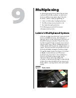
Multiplexing
Each time the operator turns the ignition key on, a complete bit test of the multiplexed system is
conducted. This test takes about 10
seconds to complete.
N
OTE
:
A flashing green light on the monitor indicates that the display power is on. This light should
be blinking steadily at 2
Hz during normal operation. If it blinks at a faster rate, it is a sign of a
problem with the monitor. A flashing red light on the monitor is also a sign of a problem. Call
Labrie
Plus
for support.
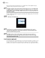
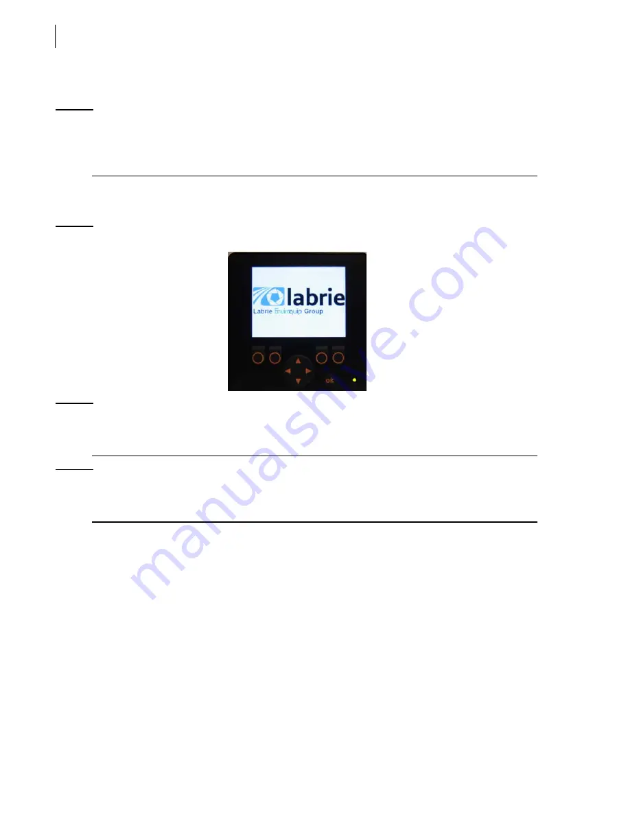
The logo of Labrie Enviroquip Group appears momentarily on the display monitor at the start of the
system (see Figure 9-2).
Figure 9-2 Labrie logo on the display monitor
N
OTE
:
If the Welcome Screen with the Labrie logo stays continually displayed, there may be a
communication problem between the monitor and the master control module. Refer this
problem to the maintenance personnel.
N
OTE
:
The display monitor works even if the engine is not started. It only needs electricity to
function. However, if you start the engine, the monitor will reboot to reflect the changes
caused by the starting of the truck.
Cart Counter (optional)
The next page that comes up after the Welcome Screen is the Cart Counter Page (see Figure 9-3). On
this page you will see the number of carts that have been emptied so far. If your vehicle is equipped
with two arms, the number of carts emptied is shown for each of these arms (right and left counters).
Summary of Contents for MINIMAX
Page 1: ...MINIMAX TM MAINTENANCE MANUAL...
Page 2: ......
Page 3: ...MINIMAX MAINTENANCE MANUAL...
Page 8: ...vi Table of Contents Adjusting Arm Speed 164...
Page 30: ...22 Safety Figure 2 17 Drain valve on air tank...
Page 72: ...64 Lubrication Figure 4 10 Lubrication chart Helping Hand arm...
Page 80: ...72 Lubrication...
Page 90: ...82 Hydraulic System Figure 5 8 Oil temp level gauge Figure 5 9 Steel hydraulic tank...
Page 102: ...94 Hydraulic System Figure 5 21 Strainer assembly Strainer...
Page 106: ...98 Hydraulic System Figure 5 25 Detecting cylinder internal leaks 1 2 3 4 5 A A A...
Page 108: ...100 Hydraulic System...
Page 113: ...Electrical System 105 Electrical Schematics Cab Adaptation...
Page 114: ...106 Electrical System Cab Console Controls...
Page 115: ...Electrical System 107 Cab Controller...
Page 116: ...108 Electrical System Chassis...
Page 117: ...Electrical System 109 Body Module rear side...
Page 118: ...110 Electrical System Body Module front side...
Page 119: ...Electrical System 111 Tailgate Lighting...
Page 120: ...112 Electrical System Panic Bars Crusher Panel Tipper Interlocks...
Page 121: ...Electrical System 113 Cameras Switchpack Details Interlocks AUTO 10 SEC INHIBIT AUTO N AUTO ON...
Page 122: ...114 Electrical System...
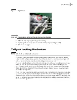
Page 127: ...Troubleshooting 119 Figure 8 4 Ball end hex wrench metric and SAE...
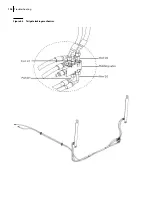
Page 134: ...126 Troubleshooting Figure 8 6 Tailgate locking mechanism...
Page 156: ...148 Multiplexing...
Page 162: ...154 Multiplexing...
Page 164: ...156 Lifting Arm Figure 10 1 Mounting bolts Figure 10 2 Helping Hand gripper Figure 10 3 Hoses...