background image

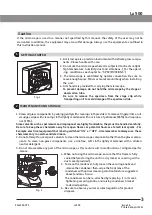
Fig. 2

Fig. 3

If the microscope is used in a manner not specified by this manual, the safety of the user may not be 
warranted. In addition, the equipment may also suffer damage. Always use the equipment as outlined in
this instruction manual.  

1. A microscope is a precision instrument with delicate glass compo-
    nents. Please handle with care.
2. Do not use the microscope where it is subjected to direct sunlight,
   high temperature, humidity, dust and vibrations. ( For the operat
    -ing   conditions, see chapter 14. “SPECIFICATIONS”)
3. The microscope is ventilated by natural convention. Be sure to
    leave enough space (10cm or more) around body when installing
    the  unit. 
4. Arm handle is provided for carrying the microscope.
   

To prevent damage, do not hold the microscope by the stage or

     observation tube. 
  Be sure to remove the specimen from the stage clip while
     transporting unit to avoid damage of the specimen slide. 


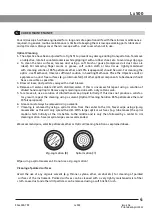
1. Clean all glass components by wiping gently with cleaning cloth provided. To remove fingerprints or oil
     smudges, wipe with cleaning cloth slightly moistened with a mixture of petroleum (85%) and isopropa-
     nol  (15%).

Since solvents such as petroleum and isopropanol are highly flammable, they must be handled carefully. 
Be sure to keep these chemicals away from open flames or potential Sources of electrical sparks - For
Example, electrical equipment that is being switched “ON” or “OFF”. Also remember to always use  these
chemicals only in a well-ventilated room.  


2. Do not attempt to use organic solvents to clean the microscope components other than the glass compo-
   nents. To clean non-glass components, use a lint-free, soft cloth slightly moistened with a diluted 
     neutral detergent. 
3. Do not disassemble any part of the microscope as this could result in malfunction or mitigated perfor
    -mance.
                                                                         4. When not using the microscope, ensure that the frame is fully 
                                                                              cooled before storing the unit in a dry locker or covering with a
                                                                              dust cover (provided).
                                                                         5.  To clean the condenser, fully loosen the securing knobs and
                                                                                remove the condenser then, wipe the front lens of the
                                                                               condenser with optical cleaning solution (mixture suggested
                                                                                above) and lens tissue.
                                                                               The condenser can be re-attached by replacing  it in its seat, 
                                                                                tightening securing knobs, and raising condenser bracket 
                                                                                to desired position.
                                                                         6.  Be sure to observe your local rules/regulation for product
                                                                              disposal.                                                           


3

Lx 500

2

1

GETTING STARTED

MAINTENANCE AND STORAGE

9144000-795

 Lx 500 

Issue 1.6

Printed on April,2022

R

Caution

Summary of Contents for Lx 500

Page 1: ... 6 Printed on April 2022 Lx 500 Research Microscopy User Manual To ensure proper use of this instrument as well as to avoid injury while operating Instrument understanding this manual completely before use is highly recommended R ...

Page 2: ... 4 Lx 500 TRINOCULAR 6 5 Lx 500 ERGONOMIC 7 6 STANDARD COMPONENTS 8 7 OPTIONAL ACCESSORIES 9 10 8 INITIAL SETUP 11 9 ASSEMBLY 12 13 10 SUMMARY OF BRIGHT FIELD OBSERVATION PROCEDURE 14 11 DETAILED OBSERVATION PROCEDURE 15 19 12 TROUBLESHOOTING GUIDE 20 21 13 SPECIFICATIONS 22 Lx 500 ...

Page 3: ...ngle quadruple nose piece has a comfortable ribbed grip for easy rotation that also safe guards the turret system against any damage All positions are par centered and par ensuring the highest level of accuracy The ball bearing mechanical stage allows smooth travel over a 76 x 50mm area with spring loaded stage clamps for retaining the specimen at the exact position desired A 0 1mm verier scale ai...

Page 4: ...n a sturdy level table or bench and avoid any restriction of air vents in the base of the unit Do not place microscope on a flexible surface as this could result in blocking the air vents and cause overheating 3 Always use the power cord provided by LABOMED If the proper power cord is not used product safety performance cannot be warranted 4 When installing the microscope route the power cord away...

Page 5: ...ch as petroleum and isopropanol are highly flammable they must be handled carefully Be sure to keep these chemicals away from open flames or potential Sources of electrical sparks For Example electrical equipment that is being switched ON or OFF Also remember to always use these chemicals only in a well ventilated room 2 Do not attempt to use organic solvents to clean the microscope components oth...

Page 6: ...ater soluble dirt with distilled water If this is unsuccessful repeat using a solution of diluted hand soap liquid Remove any remaining residue with a dry cotton swab 5 To remove oil use a solution of diluted hand soap liquid initially If this does not produce a satisfac tory result repeat the cleaning using a solvent Optical Cleaning Solution 85 petroleum ether and 15 isopropanol 6 Grease must al...

Page 7: ...mping screw Binocular viewing tube 30 inclined Eyepieces Revolving nose piece Objectives Specimen holder Abbe condenser Aperture iris Diaphragm ring Filter holder Lx 500 BINOCULAR 5 Lx 500 3 9144000 795 Lx 500 Issue 1 6 Printed onApril 2022 R Koehler mount Lamp housing on off switch AC Inlet ...

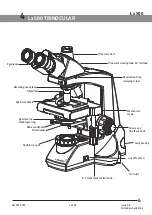
Page 8: ...ew Trinocular viewing tube 30 inclined Eyepieces Trinocular Port Revolving nose piece Objectives Specimen holder Abbe condenser Aperture iris diaphragm ring Filter holder 6 Lx 500 Lx 500 TRINOCULAR 4 9144000 795 Lx 500 Issue 1 6 Printed onApril 2022 R AC Inlet Lamp housing on off switch Koehler mount ...

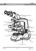
Page 9: ...Ergonomic Binocular viewing tube 0 to 25 inclined Eyepieces Revolving nose piece Objectives Specimen holder Abbe condenser Aperture iris diaphragm ring Filter holder Lx 500 ERGONOMIC BINOCULAR 7 Lx 500 5 9144000 795 Lx 500 Issue 1 6 Printed onApril 2022 Koehler mount AC Inlet on off switch Lamp housing ...

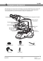
Page 10: ...t blue filter Power Cord Allen Wrench 3mm Paired Eyepieces Immersion oil STANDARD COMPONENTS After removing your microscope from its packaging you may observe the following contents Please note that the contents of your microscope may vary as the optional configuration contrasting method or viewing body opted for may not be of the standard configuration highlighted here 8 Lx 500 6 9144000 795 Lx 5...

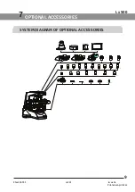
Page 11: ...BINOCULAR HEAD WF 16x RP 20x RP 50x SL OIL RP 100x SL OIL RP PH 10x RP PH 20x RP PH 40x SL RP PH 100x SL OIL RP FL 4x RP FL 10x RP FL 40x SL RP FL 20x RP FL 50x SL OIL RP FL 100x SL OIL RP 100x OIL IRIS FLIP TOP CONDENSER POLARIZER MOUNT ANALYZER MOUNT BLUE FILTER GREEN FILTER HALOGEN BULB ERGONOMIC HEAD ATLAS CMOS CAMERA CMB CAMERA ADAPTER IVU TOUCH SCREEN VEGA CMOS CAMERA ...

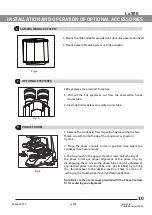
Page 12: ...here the condenser has been removed 3 The long push in to engage thumb screws on both sides of the phase turret are proper alignment of the phase ring By dis engaging these screws the phase turret can be adjusted at any desired phase annulus 10x 20x 40x 100x by turning the thumb wheel to the desired position There is also an 0 setting on the thumb wheel for bright field application Note Refer to t...

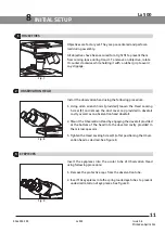
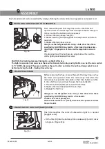
Page 13: ...provided in dovetail cavity as well as on observation head dovetail 2 Mount the Observation Head by engaging the dovetail provided at the bottom of the head into the dovetail cavity provided in the microscopes arm 3 Tighten the Head Locking Screw 1 after positioning the Obser vation head as desired See figure 8 Insert the eyepieces into the ocular tube of Observation Head using following procedure...

Page 14: ...the parts that may drop such as the filter and specimen from the microscope frame Turn the microscope to expose the base plate so that fuse holder is visible 1 Use a flat head screw driver to open the fuse holder 1 2 The fuse holder 3 will come out with dead fuse 3 Replace the dead fuse 2 with the live fuse 4 Engage the fuse tray Always use the designated Fuse Using a fuse other than those specifi...

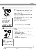
Page 15: ... 9 Reverse steps 6 to 1 to complete the process Applicable LED replacement LED P N 9135000 901 1 Screws SS 658 2 Base plate 9144000 815 3 Screws heat shield SS 714 4 Heat shield 9135000 524 5 Star LED 9135000 901 6 LED screws SS 658 7 Stand 8 Back cover plate 9126000 102 electrical panel 91260000 103 9 Decorative cap 8123000 202 1 Screws for battery cover bottom SS 658 2 Battery cover bottom 91351...

Page 16: ...the objective to be used in the light path and bring the specimen in focus Adjust the observation tube and eyepieces Adjust the interpupillary distance Adjust the dioptric setting Adjust the brightness Engage the required filters Observe Specimen A C Inlet On Off 14 Lx 500 10 SUMMARY OF BRIGHT FIELD OBSERVATION PROCEDURE 9144000 795 Lx 500 Issue 1 6 Printed onApril 2022 R ...

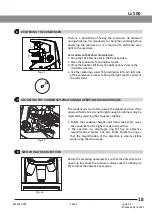
Page 17: ...ver 3 outward by pulling on lever handle 1 place the specimen by sliding the specimen glass plate s on the stage from the front toward the slide seat at the rear 3 After positioning your specimen slides 2max return the bow shaped lever 3 gently by slowly releasing control knob 1 4 Rotating the upper co axial knob controlling the y axis movement 4 moves the specimen in the vertical direction Rotati...

Page 18: ... region of interest after scanning the slide Figure 17 1 The horizontal coordinate can be read at position 1 on the specimen holder 2 The vertical coordinate can be read at the index line 2 Focusing Procedure 1 Rotate the coarse adjustment knob 1 clockwise so that the objective 3 is as close as possible to the specimen we recommend starting with 10X 2 While observing the specimen through the eyepi...

Page 19: ...red to in the future This may need when multiple users work with the microscope Procedure for adjusting the diopter 1 Rotate the right eyepiece to match the markings of your IPD If your IPD is 64 rotate the eyepiece to 0 mark 2 While looking through the right eyepiece with your right eye rotate the coarse and fine adjustment knobs to bring the Specimen into focus 3 While looking through the left e...

Page 20: ...ded on left and right side of the condenser bracket to bring the light spot to center of the view field The condenser is most often used in the highest position If the observed field of view is not bright enough brightness may be improved by lowering the condenser slightly 1 Rotate the condenser height adjustment knob 2 to move the condenser to the highest or desired position 2 The aperture iris d...

Page 21: ...r bubbles in the oil will affect the image quality make sure that the oil is free of bubbles To remove bubbles rotate the revolving nosepiece slightly to agitate the oil 4 The condenser of this microscope manifests the full perfor mance when oil is placed between the slide glass and the front lens of condenser If oil is not placed there the observed image may appear dark 5 After use remove oil fro...

Page 22: ...sion oil is not used with an immersion objective Use immersion oil as suggested Pg 19 Bubbles are present in immersion oil Remove the bubbles by agitation Pg 19 The specified immersion oil is not used Use the immersion oil supplied by LABOMED 5 Part of image is defocused Engage the objective into position until the nose turret clicks The specimen is not set properly on the stage Set the specimen c...

Page 23: ...thickness Use slides with thickness between 0 9 and 1 4mm 9 Bulb LED does not turn On Bulb is not mounted Attach a bulb Bulb is blown Replace the bulb The power cord is unplugged Firmly secure into the box socket and wall outlet Fuse is blown Check and replace with live fuse Battery is low Charge battery 10 Bulb LED blows easily The specified bulb is not used Replace with the specified bulb 8 Obje...

Page 24: ... Condenser Type Fliptop Abbe condenser daylight filter detachable N A 1 25 Aperture iris diaphragm Built in 7 Dimensions Weight 301 0mm L x 227 0mm W x 420 mm H 9kg net 8 Electrical Halogen LED 6V 30W 1 Watt Bulb Life Upto 500 hours LED 50 000 hours 9 Operating environment Indoor use Altitude Max 2000 meters Ambient temperature 5 to 40 C 41 to 104 F Maximum relative humidity 80 for temperature up ...

Page 25: ...Revision History Rev No Date of Release Change App By DCR 1 6 April 14 2022 DCR 06 22 Reviewed Up dated for typo error S Bal ...

Page 26: ...94538 U S A Phone 510 445 1257 Fax 510 991 9862 Email sales laboamerica com www laboamerica com Labomed Europe Essebaan 50 NL 2908 LK Capelle a d IJssel The Netherlands Tel 31 0 10 4584222 Fax 31 0 10 4508251 E mail info labomedeurope com EU REP ...

Reviews: