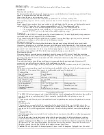
Fixing methods
Mount the amplifier on a vertical section of the mast below the antenna using the cable tie provided-fig 4
The amplifier will not be affected by proximity to the antenna, but reasonable clearance – about 300mm- should be maintained to avoid
disturbing the antennas performance.
Alternatively, the amplifier can be mounted be methods in figs 5 & 6.
Signal connections
Type-f connectors provide a reliable low-cost method of connection with excellent screening integrity and impedance match. Select the
appropriate male connectors to fit the cable type used, from ‘0.63’ to ‘233’. This method of connection is superior in all respects to saddle-
and-clamp types that it replaces. Good quality coaxial cable to EN50117-2 should be used, ideally to be used in conjunction with high quality
crimp on connectors.
Connectors should be properly fitted in accordance to manufacturer’s instructions, using the correct crimp tool.
F connectors should always be tightened with a spanner. Leaving it finger tight may result in unwanted signal ingress or leakage, as well as
suck-outs in the frequency response.
System Earth Bonding
Earth bonding terminals are provided on the amplifier casting for the use where necessary to comply with BS EN 50083-1
Technical Data
PUH141
PUH111
Operating Frequency
470-862 MHz
470-862 MHz
Number of outputs
4
1
Gain ( variable via
PSM114V) (note 1)
9-16dB
16-24dB
Filter rejection
dc….400MHz
>25dB
>25dB
Noise figure
>2.5dB
>1.6dB
Input Signal Handling
(note 3)
75dB
µ
V
77dB
µ
V
Output Signal Handling
(note 3)
99dB
µ
V
103dB
µ
V
Input Return loss
9dB
9dB
Output isolation
30dB
-
Power requirements (max
gain)
11…13V
11…13V
Current Consumption
45mA
40mA
Through line powering
No
No
EMC compliance
EN50083-2
EN50083-2
Connectors
IEC60169-24 (type f)
IEC60169-24 (type f)
Operating Temperature
-10…+40ºC
-10…+40ºC
Dimensions
142 x (W) x 86 (H) x 36
(D)
98 x (W) x 86 (H) x 36(D
Note 1: All figures apply between relevant input and each of the relevant output(s).
Note 2: Typical minimum filter rejection dc…400MHz
Note3: For 5 (max.) analogue TV signals plus 6 DVB-T multiplexes at <-14dB relative level.
Installation Instructions


