user manual
Flashline
Flashline User Manual
page 1
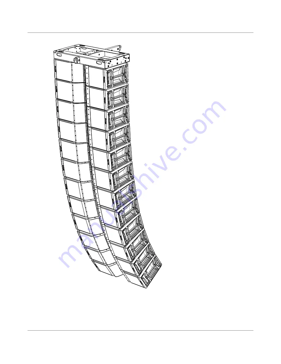
TFS-900 Flashline Loudspeaker System
User Manual
Page 1: ...user manual Flashline Flashline User Manual page 1 TFS 900 Flashline Loudspeaker System User Manual...
Page 2: ...Damping Factor in cable 14 4 3 Power Output Performance 14 5 SYSTEM CONFIGURATIONS 15 5 1 Suggested amplifier loading for the TFS 900H 15 5 2 Suggested amplifier loading for subwoofers 16 5 3 Suggest...
Page 3: ...11 4 Lake Processing and Control 43 11 5 Modules and Frames 43 11 6 LoadLibrary and Fingerprints 43 11 7 Super Modules 44 11 8 Loudspeaker Crossover Configuration Overview 44 11 9 Files and Presets 44...
Page 4: ...mains plug of the power supply cord shall remain readily operable Do not connect the unit s output to any other voltage source such as battery mains source or power supply regardless of whether the u...
Page 5: ...de d connexion ce dispositif doit demeur ais ment accessible 1 5 Caution To reduce the risk of fire or electric shock do not remove screws No user serviceable parts inside Refer servicing to qualifie...
Page 6: ...put channels on amplifiers produce high voltage do not connect or disconnect speaker cables when the mains power is on 1 7 3 Speaker Damage Amplifier apparatus is very powerful and can be potentially...
Page 7: ...updates on the technical documentation relating to this product at www turbosound com 2 2 Thanks Thank you for choosing a TURBOSOUND product for your application By engaging in an ongoing rigorous pr...
Page 8: ...loaded by Polyhorns four 6 5 horn loaded low mid cone transducers and two 12 horn loaded low frequency transducers The rigging hardware is integrated into the end cheeks on each side of the TFS 900H...
Page 9: ...0B is designed for ground stacking in support of TFS 900H cabinets and includes stacking feet and matching cabinet recesses to ensure stability Heavy duty wheels are fitted for transportation The TFS...
Page 10: ...user manual Flashline Flashline User Manual page 10 TFS 900B driver access door TFS 900B stacking foot TFS 900B NL4 connectors TFS 900B driver access door TFS 900B stacking foot...
Page 11: ...e total weight of the stack and dolly including cover is 465 5kg The heavy duty TFS COVER is designed to protect the cabinets during transit The front and rear flaps are secured with velcro and allow...
Page 12: ...i way signal connections to the rack Mil C 5015 VG 95234 The mil spec insert Number is 22 14 2 A 19 pin male C mil connector links out to additional racks 3 AES EBU One male and one female connector l...
Page 13: ...ow positive ve 2 Low negative ve 3 Mid positive ve 3 Mid negative ve 1 Bass positive ve 1 Bass negative ve 4 High positive ve 4 High negative ve 4 4 3 3 2 2 1 1 The NL4 connectors are wired as follows...
Page 14: ...e damping factor Therefore for long runs Turbosound recommends no more than two enclosures per amplifier Turbosound recommends using 4mm2 cable as standard Cable size mm2 Length for 1 x TFS 900H 8 ohm...
Page 15: ...ry the amplifier can power four enclosures this presents the bass and low mid with a 2 ohm load which does not offer optimum performance BASS loading 2 6 ohms LOW loading 2 6 ohms MID loading 4 ohms H...
Page 16: ...bwoofer has a drive unit wired to each pair of pins on the NL4 connectors Do not use the NL4 and NL8 connections simultaneously on one amplifier In this configuration speaker cable lengths should not...
Page 17: ...first NL4 on each amplifier powers the rear facing cardioid unit while the second NL4 powers the three forward facing units Do not use the NL4 and NL8 connections simultaneously on one amplifier In t...
Page 18: ...Array system Each amplifier powers three Flex Array TFA 600H cabinets and two TSW 218 subwoofers In this instance the NL4 and NL8 connections can be used simultaneously since the amplifier presets co...
Page 19: ...3 CH2 TFS 900H 6 5 low 3 2 2 20000DP 3 CH3 TFS 900H 6 5 mid 3 3 3 20000DP 3 CH4 TFS 900H 1 high 3 4 4 6 2 TFS RACK Low output routing AMP CHANNEL MAX NO OF ENCLOSURES CABINET DUTY NL8 NL8 PIN 20000DP...
Page 20: ...b 5 1 1 20000DP 3 CH2 3 TFA 600H HW 10 Lomid 3 2 2 20000DP 3 CH3 TFA 600H HW 6 5 Himid 3 3 3 20000DP 3 CH4 TFA 600H HW 1 High 3 4 4 6 4 TFS RACK Flex Array routing TSW 218 AMP CHANNEL MAX NO OF ENCLOS...
Page 21: ...S FT900 the fly trunk houses two TFS GRID flybars and associated parts such as shackles and locking bolts It is designed so as to allow the flybar to be connected and lifted out of the case with minim...
Page 22: ...ins two complete flybar assemblies and associated parts Position the TFS FT900 fly trunk directly under the motors and tip it onto one side Unlatch and remove the TFS FT900 fly trunk lid to gain acces...
Page 23: ...s in the corners 1 2 3 FRONT CLUSTER POINTS UP CLUSTER LEVEL CLUSTER POINTS DOWN FRONT FRONT Attach 3 75 tonne shackles to each end of the TFS TIP tipper bar at the lifting points Use a 1 metre steel...
Page 24: ...eel the first four TFS 900H boxes in on a TFS DOLLY and position them under the flybar Lower the TFS GRID flybar slowly into position above the loudspeaker stack and guide the drop links into the rigg...
Page 25: ...op link of the cabinet above and inserting the pin into one of the marked holes reading the required angle settings from your EASE Focus2 prediction Ensure the pin is engaged in one of the four drop l...
Page 26: ...open up as the cluster lifts clear of the TFS DOLLY depending on the angles set between them creating a gradual smooth curve to the front of the array 1 2 1 2 3 4 1 2 3 4 Fit the lower front pins on...
Page 27: ...ter to above head height Lower the rear motor only in order to bring the orientation of the lowest cabinet back to almost horizontal so that the next block of cabinets will locate more easily Wheel th...
Page 28: ...t on top of it 4 5 6 3 Locate the top rear pins on cabinet 5 in the LOCK GRID position Set the angles on cabinets 5 6 7 and 8 using the top front pins if these have not been done already Take both mot...
Page 29: ...eight is on each rigging point Carefully lower the cluster down onto a TFS DOLLY Disconnect the top pins from the fourth box Carefully raise the array to free the lower four boxes Ensure the drop link...
Page 30: ...ual page 30 7 5 Flex Array as Downfills Fles Array cabinets can be deployed at the bottom of a Flashline array as downfills using the CF 900 conversion frame CF 900 Conversion frame Flex Array TFA 600...
Page 31: ...domain and may be controlled via the Lake Controller software or front panel interface 8 1 2 2 ISVPL The Inter Sample Voltage Peak Limiter ISVPL tailors each power output to the characteristics of th...
Page 32: ...conjunction with Live Capture Light provides a completely free spectrum analyzer via your Lake Controller software interface 8 1 5 Dante Audio Network The 20000DP includes Dante digital audio networki...
Page 33: ...front panel intake to rear panel exit Please ensure that no object such as rack doors or lids are placed at the front or rear of the rack to ensure that airflow is maximized This device has no top or...
Page 34: ...user manual Flashline Flashline User Manual page 34 Figure 1 Rear Support Bracket and Mounting Hardware Figure 2 Use washer for permanent installation Figure 3 Use tube for slide on installation...
Page 35: ...quipment also uses front to rear airflow for cooling If this precaution is not observed there is a risk of overheating as units with the reverse airflow will be drawing in air which has already been h...
Page 36: ...between the device and the outside electrical environment The Iso Float feature is activated by default but may be disabled via the Lake Controller software or via the front panel menu Use correctly s...
Page 37: ...nable Select MUTE ENABLE to allow the dynamic function buttons to operate as mute controls for the Module inputs and power output channels The MUTE ENABLE button flashes when the mode is selected a su...
Page 38: ...ted in the Frame page of the Main Menu on the front panel 10 1 11 Rotary Encoder The rotary encoder is used to modify various parameters e g input level via the menu When a menu item is selected that...
Page 39: ...0 ohm termination load is enabled by default when the amplifier is the last unit connected within an AES3 daisy chained system The termination may be disabled if desired via the front panel menu and w...
Page 40: ...onnector can be used to daisy chain multiple 20000DPs LM 26 and legacy Lake devices Alternatively a Dante dual network topology can be created by connecting all secondary network connectors to a separ...
Page 41: ...X Dante Y Analog 1 2 AES 1 AES 2 Dante X Dante Y Module Gain Phase Rev Mute Output EQ Module Outpu Gain Delay Phase Rev Mute Output EQ Module Outpu Gain Delay Phase Rev Mute Output EQ Module Outpu Ga...
Page 42: ...hase Rev AMP AMP AMP ISVPL ISVPL ISVPL ISVPL Output EQ LimiterMax RMS Peak Module Output Gain Delay Phase Rev Mute Output EQ LimiterMax RMS Peak Module Output Gain Delay Phase Rev Mute Output EQ Limit...
Page 43: ...mpanying CD ROM and additional documentation is available from the Start Menu after software installation 11 5 Modules and Frames 11 5 1 Overview A Frame represents one physical Lake Processor e g a 2...
Page 44: ...ontroller Operation Manual for further information regarding Super Modules 11 8 Loudspeaker Crossover Configuration Overview The Lake Processing system may be configured with up to two inputs and up t...
Page 45: ...recalled via the front panel please refer to section 7 11 7 or via the Lake Controller software please refer to the Lake Controller Operation Manual A maximum of 100 Frame Presets can be stored on th...
Page 46: ...ler Operation Manual for further details The Lake Network Configuration Guide provides information regarding connection of one or more Lake Processors to a PC via an Ethernet network 12 3 Installing t...
Page 47: ...tup and configuration of an Ethernet network please refer to the Lake Controller Operation Manual and the Lake Network Configuration Guide 12 4 Gain Structure The 20000DP architecture provides gain ad...
Page 48: ...n settings will normally remain as defined in the file The limiter and output gain settings of the Module were configured with this gain setting and will not be automatically compensated if changes ar...
Page 49: ...r is not covered by the warranty Units on which the serial number has been removed or defaced will not be eligible for warranty service Lab gruppen shall not be responsible for any incidental or conse...
Page 50: ...ction and carefully lift out and away from the cabinet Disconnect all cables and make a note of the polarity and location for later reconnection The high frequency compression drivers high mid drivers...
Page 51: ...ersion dependent on array POWER HANDLING Optimised for 20000DP Optimised for 20000DP SENSITIVITY FULL SPACE High 111dB Mid 109dB Low 104dB Bass 10dB 107dB CALCULATED MAXIMUM SPL PER ELEMENT WHEN USED...
Page 52: ...user manual Flashline Flashline User Manual page 52 NOTES...
Page 53: ...user manual Flashline Flashline User Manual page 53 NOTES...