


3
Introduction
Thank you for purchasing a LAB.GRUPPEN power amplifier. This manual contains important information on
operating your amplifier correctly and safely. Please take some time and read this manual to familiarize yourself
with the amplifier.
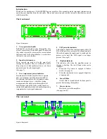
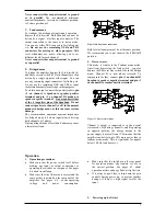
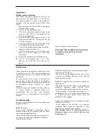
The front panel
Figure 1. Front panel
1. Carry/protection
handle
Both handles can be used to carry the amplifier, they
also act as protection for the front panel. If so desired
they can be removed (by removing the screws behind
the front panel) for fixed installations, or racks where
the front covers are to shallow.
2. Input level attenuators
These controls are used to alter the signal level
entering the amplifier. They are calibrated in dB to
help set up active loudspeaker systems or cut down
unwanted noise from the input signal.
(See page 7).
3. Over temperature protect indicator.
This indicator is lit if the amplifier tries to operate
above its maximum operating temperature(90
o
C).
The indicator first comes on as a warning to either
turn down the input level or check the cooling
arrangements after which point the amplifier will
mute the input signal. When the cooling fans have
returned the output heat sinks to the normal operating
temperature the input signal is unmuted.
4. VHF protection indicator
This indicator lights when constant signals, above 20
kHz at full power, are present at the output terminals.
When this happens the input signal is muted and the
process cycles until the VHF signal is no longer
present. (See page 8).
5. Clip/limit indicator
This indicator tells when the amplifier output is
clipping or limiting. The two different states can be
told apart:
•
When the clip limiter is engaged it flickers
briefly. (See page 8).
•
When the clip limiter is not engaged it lights for
a longer period.
6. Fan grill filter
.
A foam filter is located behind the front panel to
prevent dust entering the amplifier.
7. Power actuator
This is used to start the amplifier.
(See page 4 and 7)
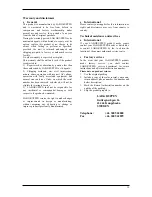
The rear panel
Figure 2. Rear panel


