NN=pmb`fcf`^qflkp==
i~ÄKÖêìééÉå== =
=
========================
NR
rëÉê=j~åì~ä===ám=QRM======sÉêëáçå=MKP========OMMPJMOJOR=
Page 1: ...m QRM rpbo j kr i...
Page 2: ...5 3 3 Tandem mode 7 5 3 4 Bridge mono mode 7 5 3 5 Bridge mono mode features 7 6 INSTALLATION 8 6 1 Mounting 8 6 2 Cooling 8 6 3 Operating voltage 8 6 4 Grounding 8 6 5 Power consumption 9 6 5 1 Calc...
Page 3: ...nding in liquid 5 Clean only with dry cloth 6 Do not block the cooling fins Install the unit in accordance with the instructions 7 Do not operate the amplifier near heat producing devices such as radi...
Page 4: ...any exposed speaker wiring while the amplifier is operating See page 11 hock about outputs for proper connection of speakers PKRKP o A sample of this product has been tested and complies with the limi...
Page 5: ...the amplifier They are calibrated in dB to assist the setup of active loudspeaker systems or cut down unwanted noise from the input signal See page 12 3 Clip limit indicator This indicator signals whe...
Page 6: ...to make sure that the unit is set up properly for your specific application RKN d The gain switch located on the rear panel the central DIP switch changes the input sensitivity of the amplifier This...
Page 7: ...ecessed one can put a sticker across the bay and prevent from unauthorized changes Another option is to remove the DIP switch This should be done by authorized service personnel only This corresponds...
Page 8: ...the remaining input connectors to carry signal to other amps Both level attenuators must be at the same position We recommend that you put them in the 0dB full position Connect the speaker as shown Al...
Page 9: ...o the AC source referred to on the label The warranty will not cover damage caused by connecting to the wrong type of AC mains If the power plug is not appropriate for your country it can be cut off a...
Page 10: ...completely obliterating the program Last the regular operating power as defined by the safety standard IEC 65 ANSI UL 6500 and used by a majority of safety agencies The regular operating power is meas...
Page 11: ...nd wired in the following way PIN 1 GROUND SHIELD PIN 2 HOT PIN 3 COLD Figure 4 XLR input connector Figure 5 XLR balanced Within the Neutrik Combojack there is a 6 3mm phone jack which is wired in par...
Page 12: ...d prevents from shock hazard They are wired in the following manner The right jack Channel A has both channel A and B outputs so it s useful for bridging and bi amp operation see bridged mono operatio...
Page 13: ...input level attenuators on the front panel adjust the signal level for their respective amplifier channel in all modes They are calibrated in dB to help setting up active loudspeaker systems or cutti...
Page 14: ...once the amplifier comes out of a protect condition the output level has a slow rise time the effect is like turning up the gain slowly VKNKO q If the amplifier is driven very hard into a low impedan...
Page 15: ...e high frequency oscillations from the relevant input Fault The amplifier goes into thermal protection when driven at low level Check that nothing causes a short circuit at the amplifier s output e g...
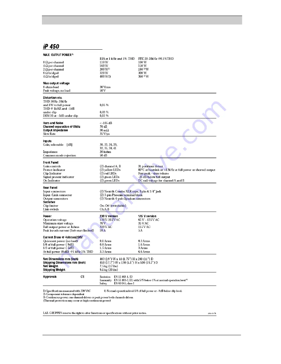
Page 16: ...NN pmb fcf qflkp i K NR r j m QRM s MKP OMMPJMOJOR...
Page 17: ...sibility for any loss due to cancellation of any events or rent of replacement equipment or costs due to third party s or customer s loss of profit or any other indirect cost or losses however incurre...