background image

9600 CB & HWG Service Manual

Page 3

SECTION 1.
General Information

1A. Introduction

The Heatmaker 9600 CB condensing boilers and

the Heatmaker 9600 HWG non-automatic circulating
tank water heaters have a dual heat exchanger (H-X)
design. The primary H-X is a copper coil type which
operates in a non-condensing mode. A secondary
stainless steel H-X (economizer) surrounds the primary
H-X to condense water vapor from the flue gases and
extract the maximum amount of heat from the
combustion process. Condensate from the economizer
drains into the bottom of the outer shroud of the boiler
section and into the exhaust duct which provides for
condensate drainage.

Flow rates through the primary H-X are

controlled by a thermostatic diverting valve which
diverts water, as required, from the outlet of the

primary H-X back to its inlet so that the primary H-X
temperature is always maintained above the
condensation temperature of the water vapor in the flue
gases. A circulator is built into the unit to provide
enough head to circulate water through the H-X’s and
to a secondary heating loop or separate hot water
storage tank.

The forced draft premixed combustion system

contains a blower to provide air flow through the unit,
the air inlet and exhaust piping. The cylindrical burner
is provided with an air/gas mixture which is metered
through fixed orifices. A hot surface igniter (glow coil)
is controlled by the Integrated Boiler Control which
also controls the blower, circulator, and gas valve and
provides for burner flame safety.

The Heatmaker 9600 is designed to use 3" PVC*

or ABS DWV pipe or PVC, ABS or CPVC schedule
40 pipe for both air intake and flue material. Vent
terminations are provided with the unit.

* CB / HWG - M2- 250 flue material can only be ABS or CPVC.
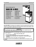
(1)

Diverting valve

(2)

Circulator

(3)

Mixer tube

(4)

Exhaust

(5)

Blower

(6)

Gas valve

(7)

Burner

(8)

Economizer

(9)

Combustion coil

(10)

Cold water inlet

(11)

Hot water outlet

(12)

Heat exchanger drain

(13)

Air vent

Figure 1. Heatmaker 9600 Assembly View.

Summary of Contents for 9600 CB

Page 1: ...r installation and or operation will void the warranty WARNING If the information in this manual is not followed exactly a fire or explosion may result causing property damage personal injury or loss...

Page 2: ...h 10 1G BoilerControl 10 1H Stack Switch 11 1I Igniter 11 1J Transformer 11 1K Unit Pump 11 1L Blower 11 1M GasValve 11 1N TimeDelayRelay TDR 11 1O OperatingControl 11 1P VentTCO 12 1Q IntakeTCO 12 1R...

Page 3: ...ondensation temperature of the water vapor in the flue gases A circulator is built into the unit to provide enough head to circulate water through the H X s and to a secondary heating loop or separate...

Page 4: ...pical D Combustion Coil Outlet E Hot Water Outlet To Tank or System 160 170 F Typical 160 FTHERMOSTAT Figure 2a Water Flow through a Heatmaker 9600 HWG Before S N 394 068 CB Before S N 795 0014 THERMO...

Page 5: ...urner 8 Secondary Heat Exchanger 9 Primary Heat Exchanger 10 Return From Primary Loop 11 Gas Valve 12 Flow To Primary Loop A Secondary Heat Exchanger Inlet B Secondary Heat Exchanger Outlet C Primary...

Page 6: ...ow Through Heatmaker 9600 43 INTAKE TERMINAL 50 WALL PLATE AIR INTAKE 45 WALL PLATE 44 EXHAUST TERMINAL EXHAUST AIR ORIFICE GAS ORIFICE GAS 1 COMBUSTION COIL 2 ECONOMIZER 7 FLAMEHOLDER 46 EXHAUST ASSE...

Page 7: ...9600 CB HWG Service Manual Page 7 Figure 4 Cut Away View of Heatmaker 9600 Figure 5 Control Box...

Page 8: ...nd input desired Part Description Part 23 Jacket Front Removeable 10 402 24 Jacket Top 10 406 25 Jacket Bottom 10 010 26 Control Boiler Integrated 2400 224 27 Transformer 40 VA 2400 006 28 Time Delay...

Page 9: ...minal and at least 6 152mm into the flue pipe The unit must operate for 5 minutes before taking a sample Take a sample and determine the CO2 or O2 CO2 8 to 8 5 natural gas O2 7 to 6 CO2 9 to 9 8 propa...

Page 10: ...ostatically controlled device which keeps the primary heat exchanger H X from operating in the condensing mode When return water from the storage tank or the system is below 130 F 54 C the diverting v...

Page 11: ...d unplug the power wires from the blower motor Disconnect intake exhaust vents and remove top jacket Remove the six bolts and nuts from the blower discharge flange and the four nuts from the blower in...

Page 12: ...n the gas valve The gas supply to the boiler must be shut off before making this connection The Heatmaker boiler is designed to operate with supply pressures of 4 14 in W C 8 1 oz in2 with the boiler...

Page 13: ...se the flame signal The control then causes a restart and if the flame signal is sensed on the restart then the burner will operate again The intermittent sending and losing of the flame signal by the...

Page 14: ...solution is no longer foamy 7 Shut off pump and disconnect from hose Carefully drain solution from hoses and connect city water to lower hose to flush combustion coil Flush for approximately 5 minutes...

Page 15: ...on and no indicator lights are flashing check for an open vent TCO operating control or safety limit switch For additionaltroubleshootinginformationrefertothe trouble shooting flow charts on the page...

Page 16: ...VOLTAGE 120 VAC BETWEEN BLACK AND WHITE WIRES AT BACK OF 120 VAC CONNECTORON BOILERCONTROL DIDBOILERRUNTHROUGHA COMPLETE CYCLE AS DE SCRIBED IN SEQUENCE OF EVENTS PAGE 20 TESTLIMIT CIRCUIT PAGE 17 PUM...

Page 17: ...OHMSCALE CONTINUITY CONTINUITY CONTINUITY NOCONTINUITY OHMS NOCONTINUITY TESTING LIMIT CIRCUIT YOU MUST COMPLETE PAGE 16 FIRST NOTE AFTER COMPLETEING LIMIT CIRCUIT TESTING PLUG IN CONTROL PLUG AND REC...

Page 18: ...EAVESETC AGAINST VENTTERMINAL CYCLE BOILER MANY TIMES TO TRY TO CREATE A MALFUNCTION CLEAR BLOCKAGE AND RECYCLEBOILER CHECKSTACKSWITCH BLOCKAGE EXISTS NO BLOCKAGE NO YES YES NO RED PURGE LIGHT FLASHIN...

Page 19: ...TSTACKSWITCH TUBES AND CHECK FOR CONTINUITYBETWEENSTACK SWITCHTERMINALSWITH BLOWEROPERATING CHECKFORVENTOBSTRUCTIONS CLEAROBSTRUCTIONS RECONNECTTUBES ELEC TRICALWIRESTOSTACK SWITCH START BOILER RUN TH...

Page 20: ...SSURETAP ON GAS VALVE PRESSURE DURING BLOWER OPERATIONWITHOUTGASFLOW VALVE FLAME LIGHT NOT LIT IS 4 IN W C CHECK FOR VOLTAGE 120 VAC ATBLOWERWIRECONNECTOR WITHIN5MINS AFTERGREEN LIGHT BLOWER O K REPLA...

Page 21: ...G LITE CHECKCOMBUSTION CHECKIGNITER IGNITEROK CHECK FOR GAS FLOW IS METER MOVING REPLACE IGNITER REPLACEINTEGRATEDBOILERCONTROLP N2400 224 INSTALL CORRECT ORIFICES BOILERCYCLESTHROUGHTHREECYCLESAFTER...

Page 22: ...L PLUG CN6 THERE IS 120 VAC AT CIRCULATOR PLUG CN5 TURNUPT STATORAQUASTATOR CORRECTSTATPROBLEM NO YES NO YES SEETROUBLESHOOTING CHART PAGE 16 THERE IS 120 VAC AT PUMP REPLACEBOILER CONTROLP N2400 224...

Page 23: ...23 Figure 9 9600 Ladder Diagram Figure 10 9600 Wiring Diagram Caution Label all wires prior to disconnection when servicing controls Wiring errors can cause improper and dangerous operation Verify pr...

Page 24: ...sure of 9 3 Remove blower and inspect flameholder burner for hole 4 Check that the blower flanges and gas piping are sealed D OCCASIONAL LOCKOUTS Requires interruption of power to re start or reset of...

Reviews: