background image


10 

3. 

Where marked, start the screw holes into the 
mounting surface. 

4. 

Screw mounting bracket onto the mounting 
surface.  Ensure that the screws are flush 
with the bracket. 

5. 

Snap the Remote Temperature Transmitter 
onto the mounted bracket. 


II. 

THE WEATHER STATION


The Weather Station can be mounted on the wall with 
the use of a wall hanging screw (not included). 


A. 

WALL MOUNTING 


1. 

Place a screw (not included) into an 
appropriate wall, leaving approximately 3/16 
of an inch (5mm) extended from the wall. 

2. 

Place the Weather Station onto the screw 
using the hanging hole on the backside.  
Gently pull the Station down to lock the screw 
into place.


BATTERY CHANGE 

Replace the batteries in all units regularly to 
ensure optimum accuracy of these units (Battery 
life See 

Specifications

 below). 


Do Not Mix Old and New Batteries 


Do Not Mix Alkaline, Standard, or 
Rechargeable Batteries 


Summary of Contents for WS-7032U

Page 1: ...WS 7032U Wireless 433 MHz Miniature Weather Station Instruction Manual ...

Page 2: ...ditional Equipment 3 Quick set up guide 3 Battery installation 4 Features 6 Indoor temperature 6 Weather Forecast icons tendency arrows 6 Outdoor temperature 8 Mounting 9 Troubleshooting 11 Maintenance and Care instructions 11 Specifications 12 Warranty 13 ...

Page 3: ...AA 1 5V batteries for weather station 2 Two fresh AA 1 5V batteries for remote transmitter 3 One Philips screwdriver QUICK SET UP GUIDE 1 Insert two AA batteries into sensor 2 Insert two AAA batteries into station 3 Wait 10 minutes to ensure transmission reception 4 Mount units in desired locations Do Not Mix Old and New Batteries Do Not Mix Alkaline Standard or Rechargeable Batteries ...

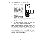
Page 4: ...thumb over the two air vent slots on the face of the Remote Temperature Transmitter push down gently slide battery cover down and off 2 Observing the correct polarity install 2 AA batteries The batteries will fit tightly to avoid start up problems make sure that they do not spring free during installation 3 Replace the battery cover ...

Page 5: ...make sure that they do not spring free during installation 4 Replace the battery cover 5 To switch between F and C press the F C button on the back of the unit Note After the batteries have been installed into the Weather Temperature Station the LCD segments should light up Within 3 minutes the Outdoor Temperature should be displayed in the OUTDOOR LCD If any of this does not occur remove all batt...

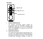
Page 6: ... or C in the INDOOR LCD The temperature is monitored as soon as the batteries are installed II WEATHER FORECAST The weather forecasting feature is estimated to be 75 accurate The weather forecast is based solely upon the change of air pressure over time The WS 7032U averages past air pressure readings to provide an INDOOR LCD FORECAST LCD OUTDOOR LCD ...

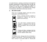
Page 7: ...CONS There are 3 possible weather icons that will be displayed in the FORECAST LCD Sunny indicates that the weather is expected to improve not that the weather will be sunny Sun with Clouds indicates that the weather is expected to be fair not that the weather will be sunny with clouds Clouds with Rain indicates that the weather is expected to get worse not that the weather will be rainy The weath...

Page 8: ...t changes in the air pressure An arrow pointing up indicates that the air pressure is increasing and the weather is expected to improve or remain good an arrow pointing down indicates that the air pressure is decreasing and the weather is expected to become worse or remain poor No arrow means the pressure is stable II OUTDOOR TEMPERATURE The Weather Temperature Station receives the outdoor tempera...

Page 9: ... facing wall The sending range is 80ft 25m obstacles such as walls concrete and large metal objects can reduce the range Place both units in their desired location and wait approximately 10 minutes before permanently mounting to ensure that there is proper reception The Weather Temperature Station should display a temperature in the OUTDOOR LCD within 3 minutes of setting up I THE REMOTE TEMPERATU...

Page 10: ...hanging screw not included A WALL MOUNTING 1 Place a screw not included into an appropriate wall leaving approximately 3 16 of an inch 5mm extended from the wall 2 Place the Weather Station onto the screw using the hanging hole on the backside Gently pull the Station down to lock the screw into place BATTERY CHANGE Replace the batteries in all units regularly to ensure optimum accuracy of these un...

Page 11: ...ce batteries Problem C is displayed instead of F or reverse Solution Press the F C button on back of station Note For problems not solved please contact La Crosse Technology MAINTENANCE AND CARE INSTRUCTIONS Extreme and sudden temperature changes vibration and shock should be avoided to prevent damage to the units Clean displays and units with a soft damp cloth Do not use solvents or scouring agen...

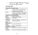
Page 12: ...h 0 2 F resolution 29 9 C to 69 9 C with 0 1 C resolution OFL displayed if outside this range Temperature checking intervals Indoor Every 10 seconds Outdoor 3 times every 10 minutes Transmitting frequency 433 92 MHz Temperature transmitting range Maximum 80ft 25m in open space and free from interference Power Source Weather Station 2 x AAA 1 5V IEC LR3 Transmitter 2 x AA 1 5V IEC LR6 Dimensions L ...

Page 13: ...ted bill of sale must be presented upon request as proof of purchase to La Crosse Technology Ltd or La Crosse Technology Ltd s authorized service center La Crosse Technology Ltd will repair or replace this product at our option and at no charge as stipulated herein with new or reconditioned parts or products if found to be defective during the limited warranty period specified above All replaced p...

Page 14: ...er 3 damage to or deterioration of any accessory or decorative surface 4 damage resulting from failure to follow instructions contained in your owner s manual 5 damage resulting from the performance of repairs or alterations by someone other than an authorized La Crosse Technology Ltd authorized service center 6 units used for other than home use 7 applications and uses that this product was not i...

Page 15: ...ives you specific legal rights You may also have other rights specific to your State Some States do no allow the exclusion of consequential or incidental damages therefore the above exclusion of limitation may not apply to you For warranty work technical support or information contact La Crosse Technology 2817 Losey Blvd S La Crosse WI 54601 Customer support www lacrossetechnology com support www ...

Page 16: ...he internal external antennas used for this mobile transmitter must provide a separation distance of at least 20 cm 8 inches from all persons and must not be co located or operating in conjunction with any other antenna or transmitter Statement according to FCC part 15 19 This device complies with Part 15 of the FCC Rules Operation is subject to the following two conditions 1 this device may not c...

Page 17: ... radio communications However there is no guarantee that interference will not occur in a particular installation If this equipment does cause harmful interference to radio or television reception which can be determined by turning the equipment off and on the user is encouraged to try to correct the interference by one or more of the following measures Reorient or relocate the receiving antenna I...

Reviews: