Installation
and Service Guide
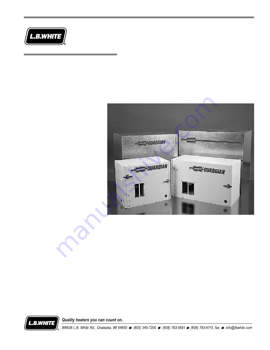
Agricultural Animal Confinement Building Heaters
150-21516
Hot Surface Ignition
Page 1: ...Installation and Service Guide Agricultural Animal Confinement Building Heaters 150 21516 Hot Surface Ignition ...
Page 2: ...tions may not necessarily depict the actual heater model and are intended for reference only It is very important when using the guide to pay particular attention to any Warning or Caution statements printed throughout the guide identifying areas where care must be exercised This Service Guide covers the majority of problems which may arise However as with any product certain problems may be encou...
Page 3: ...lead to property damage personal injury or loss of life GENERAL HAZARD WARNING Failure to comply with the precautions and instructions provided within this guide can result in Death Serious bodily injury or burns Property damage or loss from fire or explosion Asphyxiation due to lack of adequate air supply or carbon monoxide poisoning Electrical shock Read this Service Guide before installing or s...
Page 4: ...Output 3 2 Section 4 Preventative Maintenance Periodic Inspection 4 1 Cleaning Instructions 4 2 Section 5 Troubleshooting Instructions Troubleshooting Guide 5 1 Section 6 Component Testing Voltage Checks 6 1 Continuity Checks 6 2 Flame Sensor Tests 6 3 High Limit Switch Tests 6 4 Section 7 Wiring Diagrams Electrical Connection and Ladder Diagram 7 1 1 Wiring Diagrams 284 285 7 1 2 AW060 Guardian S...
Page 5: ...igh Limit Switch Replacement 8 8 Burner and Burner Orifice 8 9 Removing Control Panel Assembly on Guardian Style Heaters 8 10 Leak and Gas Pressure Checks 8 11 Section 9 Service Parts Kits and Accessories Parts Identification Guide 9 1 1 284 285 9 1 2 AB200 9 1 4 AW060 AW100 Guardian Series 9 1 6 AW075 9 1 8 AW215 9 1 10 AW230 9 1 12 AW250 Guardian Series 9 1 14 AW325 9 1 16 Kits and Accessories 9...
Page 6: ......
Page 7: ... Used for identification of model number and configuration number and also critical information such as safe clearances to combustibles burner manifold pressure maximum and minimum allowable inlet pressures etc Typical Location Interior of burner end access panel or fan motor access panel Part No Varies with design sequence and model number Contact L B White Co B Start Up and Shut Down Procedures ...
Page 8: ... 14 1 4 x 18 29 1 2 x 14 1 4 x 18 30 3 4 x 18 1 4 x 28 1 4 36 x 22 x 30 TOP 1 ft SIDES 1 ft BACK 1 ft BLOWER OUTLET GAS L P Gas Supply 6 ft 1 83 m SUPPLY Natural Gas Supply N A 52 65 116 150 57 70 126 160 AW060 AW100 AW250 AW325 L P Natural L P Natural L P Natural L P Natural Gas Gas Gas Gas Gas Gas Gas Gas M Mo od de el l Ventilation Air Required to Support Combustion Burner Manifold Pressure Net...
Page 9: ...4 36 x 22 x 30 TOP 1 ft SIDES 1 ft BACK 1 ft BLOWER OUTLET GAS L P Gas Supply 6 ft 1 83 m SUPPLY Natural Gas Supply N A 109 60 126 116 125 66 135 126 AB200 AW075 AW215 AW230 L P Natural L P Natural L P Natural L P Natural Gas Gas Gas Gas Gas Gas Gas Gas M Mo od de el l Ventilation Air Required to Support Combustion Burner Manifold Pressure Net Weight lbs Shipping Weight lbs Electrical Supply Volts...
Page 10: ...ude headaches dizziness and difficulty in breathing Symptoms of improper combustion affecting livestock can be disease lower feed conversion or death Asphyxiation H Hazard Some p people c cannot s smell w well S Some p people c cannot smell t the o odor o of t the m man m made c chemical a added t to propane LP o or n natural g gas Y You m must d determine i if y you can s smell t the o odorant i ...
Page 11: ... Electrical Features of Fuel Burning Equipment 3 Do not move handle or service heater while in operation or connected to a power or fuel supply 4 Observe and obey all instructional warnings pertaining to cleaning procedures which are located on the heater 5 For safety this heater is equipped with a manual reset high limit switch and an air proving switch Never operate this heater with any safety d...
Page 12: ... until you are sure that all gas that may have accumulated has cleared away In any event do not relight for at least 5 minutes 15 Non hanging heater installations that do not use an approved gas hose assembly must conform to local gas code requirements In absence of local codes follow ANSI NFPA58 Standard for Storage and Handling of Liquefied Petroleum Gas August 1999 ...
Page 13: ...roducts and or cause animal injury or death Critical products and or animals should be protected by a separate back up control system that limits high and low temperatures and also activates appropriate alarms 8 Take time to explain to your customer how to operate and maintain the heater by using this Service Guide Make sure your customer knows how to shut off the gas supply to the building and al...
Page 14: ...xperienced qualified LP gas installation agency b The minimum pipe size normally used in many situations is 1 2 in nominal c The information in the pipe sizing tables was obtained from Engineered Control International Inc L P Gas Serviceman s Manual L545 d Do not attempt gas supply line selection or installation unless you are properly trained and qualified e All gas supply lines must be leak chec...
Page 15: ...e August 1999 2 2 2 2 Fig 2 EXAMPLE Perform pipe sizing for building Total heat load is 1 500 000 BTUH Quantity 6 250 000 BTUH heaters Building is 300 ft long x 40 ft wide Section BTUH LP Gas Pipe Size Gas Load 5 PSIG A B 1 500 000 1 in B C 1 000 000 3 4 in C D 750 000 3 4 in D E 500 000 1 2 in E F 250 000 1 2 in B G 500 000 1 2 in G H 250 000 1 2 in First Stage Pipe Sizing 5 PSIG Inlet with a 1 P...
Page 16: ...ture is 10º F Tanks to be refilled by LP gas supplier when liquid propane level is 30 A In the 1 000 gallon tank sizing chart locate 10º F outside temperature B Locate the column which identifies 30 of propane remaining in the tank prior to refill C The intersection of these two variables identifies the heat input in BTUH that one 1 000 gallon tank can supply see shaded area in table 276 500 BTUH ...
Page 17: ...ge due to vehicular traffic or other causes it must be placed not less than two feet below grade or otherwise protected against such physical damage Regardless of its size attention must be paid to the tank distance from building openings external sources of ignition intakes to any outdoor mounted heaters or mechanical ventilation systems Refer to NFPA58 and the following illustration for the mini...
Page 18: ...r the installation may not be obtained It is almost impossible to set all regulators at the identical pressure Therefore the regulator delivering the highest outlet pressure will backpressure the other regulators in turn keeping them from operating In effect only one tank would be supplying gas to the building In this situation especially on large capacity installations ignition failures would occ...
Page 19: ...elief valve should be installed outside of building Any regulators inside the buildings must be properly vented to the outside Local state and national codes always apply to regulator installation Natural gas regulators with vent limiting device may be mounted indoors without venting to outdoors 7 All gas pressure regulators must be installed in strict accordance with the manufacturer s safety ins...
Page 20: ...eak d detectors Make certain that a sediment trap is installed at the gas valve inlet to prevent foreign materials pipe compound pipe chips and scale from entering the gas valve Debris blown into the gas valve may cause a malfunction resulting in a serious gas leak that could result in a possible fire or explosion causing loss of products building or even life A properly installed sediment trap wi...
Page 21: ...its electrical supply A properly installed three wire electrical supply consisting of separate hot neutral and ground leads shall be connected to each electrical outlet that supplies each heater Proper voltage must be supplied to each heater Proper voltage is 115 V A C 10 127 volts maximum 15 98 volts minimum Undervoltage may cause Low motor speed Igniter not reaching temperature Lack of ignition ...
Page 22: ...thermostat cord set Strip back the leads 1 4 in to expose the stranded conductors 5 Run this end of the cord up through the hole in bottom of panel from which you removed the plastic hole plug Using a pliers or other suitable tool secure the cord in place within the hole with the small strain relief that is included with the cord Install this strain relief to prevent abrasion and possible cutting ...
Page 23: ...d in place within the hole with the small plastic strain relief supplied with the thermostat kit Make sure you install this strain relief to prevent abrasion and therefore cutting the thermostat cord against the sheet metal edge of the hole 7 Locate the yellow wire which runs from the 24 v output on transformer to terminal W on the hot surface ignition control board Remove this wire 8 Connect the ...
Page 24: ... located away from the livestock so that livestock cannot knock the heater tear it loose from its mounting or damage the heater its power supply cord or its gas supply line in any way Make sure you observe and obey minimum clearance distances to combustible materials as stated in the specification section of this owner s manual and on the heater itself Hanging Instructions Installation Instruction...
Page 25: ...notched tabs on each half will pop into the blower outlet between the inside of the case assembly and the blower housing outlet If the notched tabs do not pop into the blower outlet loosen do not remove the blower outlet screws Doing this provides a gap into which you can insert the tabs b The air diverter halves are installed so the notches in the tabs are up against the formed guard of the blowe...
Page 26: ...nd close properly To prevent water entry into the case remove the cage nuts from the case top and install the hole plugs provided with the kit into each hole A sloped top accessory kit is also available for heater models AW230 and AW250 to facilitate water runoff Kit Part 500 20257 The heater should be installed at least 18 inches above the ground or to height that would prevent snow blockage at t...
Page 27: ...e motor will start up and run for five 5 seconds and then stop This pre purge is a safety feature and a normal operational characteristic prior to ignition taking place After the motor has stopped the igniter will heat up approximately 17 seconds After igniter warm up time has been achieved the motor will start again and shortly thereafter ignition will occur NOTE It is normal for air to be trappe...
Page 28: ... The throttle valve can be adjusted to deliver either minimum heat or maximum heat When the throttle valve handle is parallel to the gas flow the valve is completely open to deliver maximum heat output 3 The throttle valve may be adjusted to minimum heat output by turning the handle 90 to gas flow or any position between maximum and minimum settings August 1999 Handle Parallel Handle Turned 9 90º ...
Page 29: ...on improperly Have your gas supplier check the date codes on all regulators installed and check delivery pressures to the appliance to make sure that the regulator is reliable 5 Check all wiring associated terminals and electrical components within the heater for corrosion frayed or cut insulation tight connections etc Repair or replace as necessary 6 Review all heater markings i e wiring diagrams...
Page 30: ... fan wheel giving attention to the individual fan blades Additionally make sure the burner air inlet venturi ports and the throat of the casting are free of dust accumulation and the area between the heat chamber top and inside case is also free of dust c Observe and obey all instructional warnings pertaining to cleaning procedures which are located on the heater August 1999 WARNING Fire B Burn a ...
Page 31: ...ration sequence of the ignition module and related components is essential as it will relate directly to problem solving provided by the flow charts The ignition control module is self diagnostic The red light on the module will flash a specific pattern depending upon the problem which is diagnosed To effectively use the flow charts you must first identify what the problem is by the flashing patte...
Page 32: ...onds Two More Trials for Ignition will Occur Second Trial Follows Immediately if First Trial Fails Module Starts a 15 Minute Wait Period to Allow Ignition Interruption to Pass Third and Final Trial Occurs After 15 Minute Wait Period If Ignition Control Module Does Not Prove Flame After Third Trial the Module Goes into Safety Lockout 3 Flash Pattern Igniter Shuts Down Fan Motor Stops Gas Valve Clos...
Page 33: ...ctrical supply requirements Provide proper voltage from electrical supply Check circuit breakers in building electrical system Check power cord for continuity Replace thermostat Replace power supply switch Are 24 volts supplied from transformer Replace transformer No No No No No No Yes Are 24 volts supplied to ignition module Poor electrical connection or broken wire present Repair or replace Yes ...
Page 34: ...proving switch Rapid F F lash Reverse polarity Have electrician check neutral and hot wire connections that outlet heater is connected to Long F F lash Two seconds on two seconds off repetitively for 15 minutes Heater has attempted two ignition trials Heater is in a 15 minute wait period before attempting its third final trial for ignition If ignition is not achieved after the third trial the heat...
Page 35: ...eck for housing alignment Tighten set screw s on fan Make sure set screw s are tightened against flat s of motor shaft Yes Clean the fan wheel with compressed air or soft brush Defective motor or capacitor Replace motor Yes Remove obstruction Clean as necessary No Is fan wheel plugged with dirt No Is there an obstruction in blower outlet preventing air proving switch closure No Is proper voltage s...
Page 36: ...tlet pressure as necessary B If gas pressure is not read replace the gas control valve Defective igniter Perform continuity check and replace igniter If necessary Clean flame sensor with emery cloth or steel wool Connect igniter to igniter power supply wiring Check wiring between module and component Repair or replace as necessary or replace control module Provide proper pressure to heater and che...
Page 37: ...repaired if a problem is found 2 IMPORTANT Remember the ignition control board sends and receives voltages throughout the entire operation sequence The ignition control board terminals should also be checked for delivering proper voltages in addition to the individual components as indicated by the respective flash pattern to make sure the board itself is working properly 3 In order to verify the ...
Page 38: ......
Page 39: ...both past and present designs of control modules Refer to the following illustrations for comparison of ignition controls and positioning of designators which in turn will identify the voltage that each individual component receives Component Testing Part 120 0 09298 Part 120 0 08117 Self D Diagnostic C Control M Module T Terminal Designators a and V Voltages Part 120 0 09298 a and 1 120 0 08117 I...
Page 40: ...o high limit switch and finally to control module TR Neutral return for transformer MV Neutral return for control valve MV 24 V A C to gas control valve Control M Module Part 120 0 08027 A AT TT TE EN NT TI IO ON N The control module has three diagnostic light patterns No Light Normal operation Steady On Light Fault is internal to module Replace module Flashing Light Problem is within other heater...
Page 41: ...e black motor wire and the other probe to ground When the module is energized you will see approximately 120 volts readout on the meter display This verifies the module is supplying voltage and the wiring between the module and the motor is in good condition Checking f for v voltage s supply t to i igniter f from module Apply the probes to the female terminals in the plastic connector at the end o...
Page 42: ... s scale Place the tester probes on the terminals of the component being tested If your meter has an audible continuity feature you will hear a ringing sound in addition to seeing a read out in ohms Examples of checking for continuity on several components are shown Typically components which show an open circuit and are not in proper working order will exhibit an overload readout on the display o...
Page 43: ...erature and open when the temperature is achieved This will allow the heater to cycle accordingly Refer to the heater wiring diagram or the wiring diagram applied to the inside of the thermostat cover for proper hook up Component Testing August 1999 6 2 2 2 appear on the tester indicating that there is a completely closed electrical circuit through the cordset and thermostat Thermostat Continuity ...
Page 44: ...er supply wire from module and performing the following Shut the heater off Set your multimeter to A C Connect one probe to the exposed terminal at the end of the wire from terminal FSI and the other probe to ground sheet metal screw or cabinet Turn the heater on As soon as there is a call for heat the control module will start sending approximately 100 V A C or 24 V A C to the sensor depending on...
Page 45: ...1 Disconnect flame sensor wire from terminal FSI on the ignition control module 2 Connect the male terminal from the transducer to the female terminal of the flame sensor wire Connect the female terminal of the transducer to the male terminal at terminal FSI on the control module 3 Reconnect heater to electrical supply C Flame S Sensor C Check 1 Start the heater and allow the ignition sequence to ...
Page 46: ...m the switch which indicates the electrical contacts have opened Let the switch cool down for about 10 20 seconds before firmly pressing the reset button on the switch Check for continuity across the terminals of the switch to make sure the contacts are closed Reinstall the switch into the heater and reconnect heater to its electrical supply ATTENTION Model AB200 heaters incorporate a high limit s...
Page 47: ...er s electrical connection diagram when servicing to avoid wiring errors and heater malfunction Check for proper operation after servicing Without C Configuration N Number MODEL AW075EHP3 SERIAL NO L B WHITE CO INC W6636 L B WHITE ROAD ONALASKA WI 54650 608 783 5691 A G S DESI GN CER TI FI ED A A A MERI C N SSO C I ATI O N MAXIMUM INPUT 75 000 BTUH TYPE FUEL PROPANE VAPOR WITHDRAWAL BURNER MANIFOL...
Page 48: ...TE BLACK 24VAC TRANS 120VAC BLACK BLACK WHITE BLACK BLACK BLACK WHITE WHITE BLACK POWER CORD 120VAC TERMINAL BOX 24VAC TERMINAL BOX GROUND GREEN BLACK BLACK AIR PROVING SWITCH HIGH LIMIT SWITCH BLACK BLACK THERMOSTAT L1 GREEN MOTOR HIGH LIMIT SWITCH TRANSFORMER 120V 24V NEUTRAL HOT SURFACE IGNITER HSI CONTROL AIR PROVING SWITCH SOLENOID S FLAME SENSOR MV MV TR TH FP GRD L1 IGN ELECTRICAL LADDER DI...
Page 49: ...TCH HIGH LIMIT SWITCH FLAME SENSOR HEAT CHAMBER OR BURNER GROUND IGNITER GAS CONTROLVALVE THERMOSTAT BROWN GREEN GREEN BROWN WHITE RED RED BROWN GREEN YELLOW YELLOW YELLOW YELLOW GREEN WHITE GREEN ON OFF TERMINAL STRIP JUMPER SEE NOTE NOTE REMOVE JUMPERTO ADDTHERMOSTAT BLACK WHITE WHITE BLACK WHITE BLACK WHITE BLACK YELLOW WHITE WHITE BLACK BLACK WHITE ON OFF SWITCH BLACK BLACK WHITE WHITE GREEN L...
Page 50: ...N FLAME SENSOR HEAT CHAMBER OR BURNER GROUND IGNITER GREEN RED RED GREEN WHITE BROWN WHITE BLACK YELLOW YELLOW BLACK WHITE GROUND GREEN GREEN WHITE BLACK BLACK WHITE YELLOW YELLOW GREEN GREEN WHITE BLACK S W I T C H ON OFF WHITE BLACK WHITE WHITE BLACK TERMINAL STRIP WHITE BLACK NOTE REMOVE JUMPERTO ADDTHERMOSTAT JUMPER SEE NOTE GREEN BROWN YELLOW YELLOW WHITE BLACK GAS CONTROLVALVE THERMOSTAT WHI...
Page 51: ... GAS CONTROLVALVE AIR PROVING SWITCH GROUND L1 NEUTRAL THERMOSTAT NEUTRAL GROUND HIGH LIMIT SWITCH BURNER GROUND SOLENOID S AIR PROVING SWITCH FLAME SENSOR L E D INDICATOR HSI CONTROL MOTOR TRANSFORMER 120V 24V IND L1 HSI HSIG L2 W PSI FSI GV PSO FSG C BROWN WHITE GREEN BLACK WHITE BLACK GREEN GREEN RED RED PURPLE WHITE BROWN BROWN BLACK WHITE BLUE BLUE BLACK BLACK WHITE WHITE WHITE BLACK GREEN YE...
Page 52: ...TERMINAL STRIP WIRING NOT SUPPLIED WITH UNIT NOTE REMOVE JUMPERTO ADDTHERMOSTAT GROUND BLACK RED GREEN YELLOW YELLOW YELLOW GREEN WHITE BLACK RED S W I T C H ON OFF RED BLACK BLACK YELLOW JUMPER SEE NOTE WHITE BLACK RED WHITE WHITE BLACK YELLOW YELLOW BLACK RED RED WHITE BLACK BLACK BLACK WHITE BLACK RED BROWN BROWN WHITE GREEN GREEN RED RED BROWN GREEN BLACK BLACK RED WHITE WHITE YELLOW BLACK RED...
Page 53: ...ACK BLACK BLACK RED RED RED RED RED RED WHITE WHITE WHITE RED YELLOW YELLOW YELLOW IND L1 HSI HSIG L2 W PSI FSI GV PSO FSG C BLACK BLACK RED RED WHITE YELLOW YELLOW WHITE BROWN YELLOW GREEN GREEN YELLOW RED BLACK BROWN BROWN BLACK WHITE BROWN GREEN GREEN GREEN RED RED WHITE YELLOW WHITE BLACK WIRING SUPPLIEDWITH OPTIONALTHERMOSTAT WHITE BLACK BLACK RED WHITE GREEN GROUND L2 NEUTRAL L1 HOT L2 HOT W...
Page 54: ......
Page 55: ...ges the air proving switch arm thereby closing the switch contacts establishing that the motor is up to full speed and sufficient airflow is present B Air P Proving Safety device that proves that proper Switch motor speed and airflow is being achieved before the gas control valve is opened Some air proving switches incorporate a paddle welded onto its arm whereas others work in conjunction with a ...
Page 56: ... established G Gas C Control V Valve A device which consists of a low pressure regulator and electrical solenoids which are used for the control of gas flow to the burner assembly A feature of the control is a built in gas shut off which is used to isolate the heater from its gas supply when servicing H Gas H Hose Flexible connector used to convey gas from gas supply line on building to heater I H...
Page 57: ...s Ignites gas by surface temperature rather than by spark or flame L Ignition C Control Controls the ignition sequence and Module operation of the heater as well as monitoring the safety devices A major service feature is the board s ability to diagnose component and flame failure by means of a diagnostic light located within the module This light will provide a specific flash pattern repetitively...
Page 58: ...rough the burner at the stated manifold pressure see dataplate to achieve proper heat output R Regulator Mechanical devices used in gas distribution systems Its purpose is to reduce a higher inlet pressure to a preset lower pressure The regulator is responsible to supply a steady outlet pressure to the heater s despite changes in inlet pressure heater demand and weather conditions S Thermostat Ele...
Page 59: ... wiring 3 Position the replacement module near the module in the control box 4 Transfer the electrical leads one at a time from one module to the other by matching up the wiring designators until all leads are reconnected to the proper designator on the replacement module 5 Remove the mounting screws that secure the module to the control box 6 Mount the replacement module in the control box using ...
Page 60: ...w steps 1 5 above 2 Loosen the set screw s on the fan wheel 3 Pull the fan wheel from the motor shaft Use a wheel puller if necessary All L B White fan wheels incorporate a wheel puller groove on the fan hub to assist in fan removal 4 Remove the nuts that hold the mounting plate to the motor 5 To reinstall motor and wheel reverse these procedures IMPORTANT Make sure that the fan does not rub on th...
Page 61: ...cts closing within the switch 4 If the switch contacts do not close within this distance then manually push in the switch arm to make sure the switch is not defective If a click is heard normally the switch is good and the sail arm then needs to be adjusted If in doubt check for continuity 5 Using a needle nose pliers gently bend up the arm of the flapper NOT T THE S SWITCH A ARM in increments unt...
Page 62: ...e switch in place using the two remaining nuts NOTE When replacing the switch make sure the arm of the switch is located above the flapper arm Air Proving Switch Servicing Instructions For H Heaters w with A Air P Proving S Switch a and P Paddle 1 Shut off gas supply to heater and disconnect heater from its power source 2 Open case access panel on fan motor end of heater 3 Remove two 2 sheet metal...
Page 63: ...ounting bracket 5 Connect the replacement igniter to its power supply wiring 6 Slide the igniter and igniter shield down over the mounting screw so the mounting slots of these components straddle the screw 7 Tighten the screw snugly DO NOT OVERTIGHTEN Overtightening can cause cracks in base of igniter possibly leading to future igniter failure August 1999 Connectors Igniter Shield Heaters w with C...
Page 64: ...odel 3 Disconnect the sensor from the supply wiring 4 Replace with new sensor For units with cast burner the sensor tip must be properly positioned within the burner flame Normally 1 2 in is sufficient On units with a burner plate the sensor is pre formed and will be self located when remounted back onto the support bracket The clearance of the sensor rod to burner plate on the burner flame side o...
Page 65: ... with model and design Refer to appropriate parts list for part number Other heater designs may have the switch mounted without spacers directly to the flat of the heat chamber face or to formed offsets which act as spacers Familiarize yourself with switch mounting characteristics Specifically relating to the AB200 heater the high limit consists of capillary and switch mounted to a bracket near th...
Page 66: ...position the spacers as illustrated Do not kink the capillary tube or pinch it between the formed tabs and the heat chamber by using unnecessary force Capillary damage with subsequent switch failure will occur Capillary R Resting on S Spacer Capillary R Routed Beneath S Spacer Dashed L Line Indicates Routing o of Capillary Behind Burner 12 Formed Tabs Spacer ...
Page 67: ... over the control valve if applicable 6 The gas control valve with manifold can now be readied for removal from the heater This procedure varies slightly depending on model and age of the heater Some models allow the valve to be removed from its metal enclosure by removing two screws that can be accessed at the control valve inlet Other models may require removal of the valve enclosure mounting sc...
Page 68: ... of dust Brush or blow off as necessary If it still appears plugged remove and inspect the burner orifice Blow out the orifice hole with compressed air until the hole is open Also inspect the manifold area into which the orifice was threaded to make sure there aren t any blockages If necessary remove that portion of the manifold and clean it also 12 Reassemble all components Use pipe thread compou...
Page 69: ...move the orifice pry off either of the retaining rings holding the orifice in place The replacement orifice ships with both bowed and flat retaining rings The flat retaining ring holds the orifice on the flame side of the burner plate The bowed retaining ring holds the orifice in place on the gas inlet side of the orifice 6 Reassemble all components 7 Restart the heater Check for proper burner fla...
Page 70: ...eater and disconnect the heater from its electrical supply 2 Remove the top two sheet metal screws on each side of the control box 3 Loosen the bottom screw on each side of the control box 4 Pivot the control box forward exposing the wire harness connector socket Turn the wire harness connector with 9 female pins socket located on back of box counter clockwise 5 Remove the bottom screws from each ...
Page 71: ...pable of reading up to 35 in W C 2 Disconnect the heater from the electrical supply and close the fuel supply valve to the heater inlet 3 Open or remove the burner access panel if applicable Remove the protective cover from over the control valve 4 Brush or blow off any dust and direct on or in the vicinity of the gas control valve B Gauge I Installation 1 Locate the inlet and outlet pressure taps...
Page 72: ...et and outlet connections with approved gas leak detectors f If a leak is detected disconnect the heater from its electrical supply and close the fuel supply valve to the heater g Check the components involved for cleanliness in the thread areas and proper application of pipe compound h Tighten the gas connection as necessary to stop the leak If necessary replace the parts or components involved i...
Page 73: ... on a Remove the regulator cap on the control valve to expose the output pressure adjusting screw Valve shown outside of heater for clarity of viewing b Using a standard screwdriver turn the plastic adjusting screw until the gauge reads proper manifold pressure Clockwise increases outlet pressure Counterclockwise will decrease pressure c Reinstall regulator cap on valve NOTE Procedures for adjusti...
Page 74: ......
Page 75: ...TI FI ED A A A MERI C N SSO C I ATI O N MAXIMUM INPUT 75 000 BTUH TYPE FUEL PROPANE VAPOR WITHDRAWAL BURNER MANIFOLD PRESSURE 11 IN W C AT MAXIMUM INPUT ELECTRICAL 115 VOLTS A C 60 HZ SINGLE PHASE 1 4 AMPS MIN CLEARANCES FROM HEATER TO ADJACENT COMBUSTIBLE MATERIALS REAR 1 FT SIDES 1 FT TOP TO CEILING 1 FT BLOWER OUTLET 6 FT AND FUEL CONTAINER 6 FT VENTILATION 450 CFM OF AIR REQUIRED TO SUPPORT CO...
Page 76: ...der O Orifice X 310 0 02690 13 Orifice B Burner LP G Gas X 310 0 02691 Orifice B Burner Natural G Gas X 310 0 02735 14 Bolt X 130 0 02692 15 Transformer X 120 0 06979 16 Control H Hot S Surface I Ignition X 550 0 08027 17 Harness I Igniter W Wire X 120 0 06068 18 Burner X 320 0 03453 19 Shield I Igniter X 240 0 09167 20 Igniter K Kit 2 500 0 09755 21 Sensor F Flame X 120 0 06165 22 Screw B Burner ...
Page 77: ...rts Kits and Accessories 6 SEDIMENT TRAP KIT OPTIONAL ACCESSORY 4 5 14 42 41 3 2 1 8 7 9 40 25 N G SUPPLY 10 11 12 17 18 20 13 15 19 27 26 21 24 22 23 28 29 32 33 31 30 39 36 34 35 37 38 16 Model 2 284 285 Parts Identification Guide ...
Page 78: ... X 225 0 09513 14 Shield I Igniter X X N A 240 0 08001 Shield I Igniter N A N A X 240 0 09167 15 Igniter X X N A 500 0 09755 Igniter N A N A X 550 0 09201 16 Sensor F Flame X X X 120 0 08270 17 Bracket I Igniter a and S Sensor X N A N A 260 0 07110 Bracket I Igniter a and S Sensor N A X X 260 0 08233 18 Burner X X X 320 0 03453 19 Spacer B Burner X X X 130 0 02687 20 Bracket I Ignition C Control M...
Page 79: ...999 9 1 5 5 1 2 3 5 4 6 7 8 9 10 10 11 11 12 12 13 13 14 14 15 15 16 16 17 17 18 18 19 19 21 21 22 22 23 23 26 26 24 24 30 30 31 31 37 37 33 33 34 34 35 35 36 36 38 38 27 27 28 28 29 29 32 32 25 25 26 26 Model A AB200 Parts Identification Guide ...
Page 80: ...01 20 Flame S Sensor X 120 0 09626 21 Bracket I Igniter a and S Sensor X 260 0 09932 22 Burner X 320 0 09933 23 Switch H High L Limit X 120 0 03933 24 Spacer X 130 0 02687 25 Chamber H Heat 6 60 000 B Btu X 400 0 09652 Chamber H Heat 1 100 000 B Btu X 400 0 09664 26 Case A Assembly w w Doors a and L Latches 6 60 000 B Btu 2 X 400 0 09655 Case A Assembly w w Doors a and L Latches 1 100 000 B Btu 2 ...
Page 81: ... 40 39 38 37 36 35 32 33 34 30 29 28 27 26 25 24 23 22 20 21 19 18 13 12 11 17 16 15 14 10 9 8 7 6 4 3 2 1 31 5 Service Parts Kits and Accessories Guardian A AW060 A AW100 August 1999 9 1 7 7 Parts Identification Guide ...
Page 82: ...X 310 0 08357 Orifice B Burner N Natural G Gas X X X X X 310 0 08358 23 Igniter 1 1 N A N A N A 500 0 09755 Igniter N A N A X X X 500 0 09201 24 Burner P Plate A Assembly w w Orifice X X X X X 400 0 09215 24 Chamber H Heat X X X X X 220 0 08670 25 Chase W Wire X X X X X 225 0 08294 26 Chamber H Heat X X X X X 220 0 08670 27 Case A Assembly w with D Doors a and L Latches 2 X X X X X 500 0 08494 28 ...
Page 83: ... 3 2 46 45 44 38 43 42 33 32 41 39 40 37 36 35 34 31 30 29 28 27 26 25 23 24 22 21 20 19 18 17 16 16 15 15 14 13 12 11 10 9 8 7 6 Service Parts Kits and Accessories Model A AW075 August 1999 9 1 9 9 Parts Identification Guide ...
Page 84: ...N A 225 0 08325 Bracket G Gas C Control N A X 225 0 09506 11 Manifold X X 130 0 07825 12 Orifice B Burner L LP G Gas X X 310 0 07717 Orifice B Burner N Natural G Gas X X 310 0 07816 13 Shield I Igniter X X 240 0 08001 14 Igniter K Kit 500 0 09755 15 Sensor F Flame w w Lead X X 120 0 08273 16 Bracket I Igniter a and S Sensor X X 260 0 08233 17 Burner X X 320 0 03453 18 Spacer X X 130 0 02687 19 Cha...
Page 85: ...6 16 17 17 18 18 11 11 12 12 20 20 19 19 22 22 27 27 28 28 37 37 21 21 35 35 30 30 25 25 24 24 26 26 29 29 23 23 31 31 32 32 33 33 34 34 36 36 TO SEDIMENT TRAP TO SEDIMENT TRAP Service Parts Kits and Accessories August 1999 9 1 1 11 Parts Identification Guide ...
Page 86: ... G Gas X X X N A 410 0 08519 Valve T Throttle N Natural G Gas N A N A N A X 410 0 09606 15 Manifold N A X X X 420 0 09291 Manifold S Single P Piece U U S Shaped not i illustrated X N A N A N A 130 0 09019 16 Orifice B Burner L LP G Gas X X X N A 310 0 08705 Orifice B Burner L LP G Gas N A N A N A X 310 0 09603 Orifice B Burner N Natural G Gas X X X N A 310 0 08706 Orifice B Burner N Natural G Gas ...
Page 87: ...13 33 33 34 34 36 36 35 35 25 25 40 40 39 39 38 38 37 37 27 27 29 29 26 26 30 30 31 31 32 32 28 28 22 22 10 10 23 23 21 21 24 24 20 20 16 16 17 17 19 19 9 18 18 15 15 14 14 13 13 12 12 11 11 41 41 8 7 6 5 4 4 3 2 1 Model A AW230 Parts Identification Guide ...
Page 88: ...LP G Gas X 310 2 20141 Orifice B Burner N Natural G Gas X 310 2 20142 16 Igniter X 120 0 09201 17 Shield I Igniter X 240 0 09167 18 Sensor F Flame X 120 2 20139 19 Bracket I Igniter X 260 0 09202 20 Burner X 320 0 03453 21 Spacer X 130 0 02687 22 Switch H High L Limit X 120 0 05566 23 Chamber H Heat X 400 2 20024 24 Case A Assembly w with D Doors a and L Latches X 225 2 20149 25 Harness 9 9 w wire...
Page 89: ...1 15 30 30 23 23 19 19 18 18 17 17 38 38 37 37 35 35 36 36 27 27 26 26 25 25 34 34 32 32 31 31 33 33 28 28 29 29 24 24 22 22 21 21 16 16 20 20 15 15 14 14 11 11 13 13 12 12 10 10 9 7 6 5 4 4 3 2 1 39 39 40 40 Guardian A AW250 Parts Identification Guide ...
Page 90: ... C Control X N A 225 0 08513 Cover G Gas C Control N A X 225 0 09287 11 Bracket G Gas C Control X N A 225 0 08512 Bracket G Gas C Control N A X 225 0 09506 12 Base X N A 225 0 08644 Base N A X 225 0 09674 13 Manifold X X 130 0 09019 14 Orifice B Burner L LP G Gas X N A 310 0 08928 Orifice B Burner N Natural G Gas X N A 310 0 08694 Orifice B Burner L LP G Gas N A X 310 0 09694 Orifice B Burner N Na...
Page 91: ...ts and Accessories August 1999 9 1 1 17 1 2 3 4 5 24 30 31 33 28 27 29 32 25 6 7 8 9 10 11 12 13 14 15 16 17 22 20 19 18 21 26 38 34 35 36 37 39 23 TO SEDIMENT TRAP 40 42 41 43 Model A AW325 Parts Identification Guide ...
Page 92: ...ER DESIGN S 500 08570 AB200 A B 500 09539 AB200 C 500 20118 AW060 A 500 08598 AW075 All 500 20116 AW100 A 500 08595 AW215 B 500 09540 AW215 C 500 09324 AW230 C D 500 09541 AW230 E F 500 20258 AW250 A 500 09833 AW325 A 500 20114 AW325 B NATURAL G GAS T TO P PROPANE 500 08594 AB200 A B 500 09542 AB200 C 500 20119 AW060 A 500 08599 AW075 All 500 20117 AW100 A 500 08596 AW215 B 500 09543 AW215 C 500 0...
Page 93: ...s Steel w 25 Cord Wired to Control Panel Remote Thermostat Nema 4X w 25 Cord Wired to Control Panel DESCRIPTION Two Piece Snap In 500 06537 500 00831 500 09454 500 09381 500 20177 500 20176 T Duct 105 Duct Flush Mount Diffuser MISCELLANEOUS A ACCESSORIES PART NUMBER 500 07802 Indoor Chain Hanging Kit All 500 20257 Sloped Top for Outdoor Mount AW230 AW250 DESCRIPTION MODEL OUTDOOR M MOUNTING K KITS...
Page 94: ......
Page 95: ...m t the d date o of p purchase b by the e end u user Warranty is automatic if a component is found defective within 12 months of the date code marked on the part If the defect occurs more than 12 months later than the date code but within 12 months from the date of purchase by the end user a copy of a bill of sale will be required to establish warranty qualification The warranty set forth above is...
Page 96: ...e available from L B White upon request B By using the Return Authorization Number procedure described in A above All items must be returned freight PREPAID Out of warranty parts require factory approval and a Return Authorization Number prior to being returned 3 Credit Credit will be issued if inspection indicates A The item is defective B The item is within the warranty period C Failure is due t...