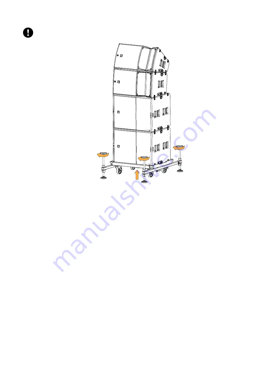
Rigging procedures
4.
Rotate the wheels clockwise to raise the array.
Stop raising the stack as soon as the wheels get off the ground.
56
KS21 owner's manual (EN) version 2.1
Page 1: ...KS21 owner s manual EN ...
Page 2: ...anual EN version 2 1 Distribution date September 30 2019 2019 L Acoustics All rights reserved No part of this publication may be reproduced or transmitted in any form or by any means without the express written consent of the publisher ...
Page 3: ...rays 14 A15 BUMP 14 A15 RIGBAR 16 Rigging elements for stacked arrays 18 KS21 OUTRIG 18 K2 JACK 19 Storage and handling elements 21 KS21 CHARIOT 21 KS21 PLA 22 KS21 COV and KS21 CHARIOTCOV 23 Mechanical safety 24 Loudspeaker con gurations 26 KS21 in standard con guration 26 KS21 in cardioid con guration 27 Inspection and preventive maintenance 28 How to do preventive maintenance 28 Rigging part in...
Page 4: ... with A15 BUMP A15 RIGBAR 47 Stacking 52 Stacking KS21 on KS21 CHARIOT 52 Attaching K2 JACK stabilizers to KS21 CHARIOT 54 Connection to LA ampli ed controllers 57 Corrective maintenance 58 Speci cations 63 APPENDIX A Recommendation for speaker cables 71 4 ...
Page 5: ...are familiar with the rigging techniques and safety recommendations outlined in this manual Ensure personnel health and safety During installation and set up personnel must wear protective headgear and footwear at all times Under no circumstances is personnel allowed to climb on a loudspeaker assembly Respect the Working Load Limit WLL of third party equipment L Acoustics is not responsible for an...
Page 6: ... continuous evolution of techniques and standards L Acoustics reserves the right to change the speci cations of its products and the content of its documents without prior notice Check www l acoustics com on a regular basis to download the latest document and software updates Read the maintenance section of this document before servicing the product Do not expose the product to extreme conditions ...
Page 7: ...anical safety p 24 Loudspeaker con gurations p 26 3 Before rigging the system perform mandatory inspections and functional checks Inspection and preventive maintenance p 28 4 To deploy the system follow the step by step rigging instructions and refer to the cabling schemes Rigging procedures p 47 Connection to LA ampli ed controllers p 57 The Corrective maintenance p 58 section contains the operat...
Page 8: ...4 2 point speakON Information about the connection of the enclosures to the LA ampli ed controllers is given in this document Refer to the LA4X LA8 LA12X user manual for detailed instructions about the whole cabling scheme including modulation cables and network Rigging elements A15 BUMP Flying frame for vertical deployment of A15 and KS21 A15 RIGBAR Rigging bar and pullback for A15 and KS21 KS21 ...
Page 9: ...System components Loudspeaker cables 0 7 m 5 m 10 m 25 m CH 1 CH 2 1 m SP 7 SP5 SP10 SP25 SP Y1 0 7 m 10 m 25 m SPK1 SPK2 SPK3 SPK4 5 m DO 7 DO10 DO25 DOSUB LA8 KS21 owner s manual EN version 2 1 9 ...
Page 10: ...System components Rigging elements A15 BUMP A15 RIGBAR KS21 OUTRIG KS21 CHARIOT K2 JACK CLAMP250 KS21 PLA KS21 COV KS21 CHARIOTCOV 10 KS21 owner s manual EN version 2 1 ...
Page 11: ...0 dB 0 ms ON OUT 4 SB IN A 0 dB 0 ms ON KS21_60_C KS21_100_C KS21_60_Cx KS21_100_Cx loudspeaker elements outputs channels routing gain delay polarity mute SR OUT 1 SR ON SB OUT 2 SB ON SB OUT 3 SB ON SB OUT 4 SB IN A 0 dB 0 ms ON Connectors KS21 2 4 point speakON Internal pinout for L Acoustics subwoofers speakON points 1 1 2 2 Transducer connectors LF LF Not linked Not linked KS21 owner s manual ...
Page 12: ...tating rigging arm A spring loaded pin Push and slide to unlock the spring loaded pin SHLAK The rigging elements are tted with yellow safety labels that are visible when they are not safely locked KS21 displays two ground runners on the bottom and two matching tracks on the top 12 KS21 owner s manual EN version 2 1 ...
Page 13: ...otated to adapt to every con guration KS21 features a 35 mm pole socket which contains an M20 150 insert Use a 35 mm diameter pole The pole can be non threaded or with M20 thread Use an adapter for poles with other dimensions for example the 21329 adapter by K M available on www k m de en KS21 owner s manual EN version 2 1 13 ...
Page 14: ...KS21 CHARIOT and KS21 PLA Use with other equipment may result in instability causing injury Rigging elements for own arrays A15 BUMP A15 BUMP is a reversible rigging frame for ying vertical arrays of KS21 A15 BUMP is equipped with rotating rigging arms and ball locking pins to match the rigging systems of KS21 on either side 14 KS21 owner s manual EN version 2 1 ...
Page 15: ...F and one rear pickup point R are available for site angle adjustments They are compatible with Ø12 mm shackles WLL 1 t two provided and CLAMP250 1 2 3 4 5 6 7 8 9 10 11 12 13 14 15 16 F R FRONT 1 2 3 4 5 6 7 8 9 10 11 12 13 14 15 16 A15 BUMP can be used as the main lifting accessory for ying vertical arrays of KS21 with one or two lifting points KS21 owner s manual EN version 2 1 15 ...
Page 16: ... for ying vertical arrays of up to four KS21 A15 RIGBAR is equipped with rotating rigging arms and ball locking pins to match the rigging systems of KS21 on either side The rigging arms are tted with yellow safety labels that are visible when the rigging arm is not in use 16 KS21 owner s manual EN version 2 1 ...
Page 17: ...r two lifting points The pickup points are compatible with Ø12 mm shackles WLL 1 t two provided and CLAMP250 When using A15 RIGBAR as the main lifting accessory always implement a secondary safety using available holes One pickup point safety points pickup point Two pickup points pickup points safety point KS21 owner s manual EN version 2 1 17 ...
Page 18: ... stability bars for KS21 Secure KS21 OUTRIG at the bottom of a KS21 array to improve the stability of the array The use of KS21 OUTRIG is mandatory when A15 Wide Focus or A10 Wide Focus are stacked on top of KS21 KS21 OUTRIG matches the rigging system of KS21 SHLAK 18 KS21 owner s manual EN version 2 1 ...
Page 19: ... K2 JACK K2 JACK is a set of two bars and four feet with screw jacks and hand wheels K2 JACK can be tted onto KS21 CHARIOT p 21 to improve stability or correct oor discrepancies During transportation make sure the bolts are tightened bolts x4 feet with screw jacks locking handles hand wheels storage position position in use KS21 owner s manual EN version 2 1 19 ...
Page 20: ...Rigging system description 20 KS21 owner s manual EN version 2 1 ...
Page 21: ...re the lower KS21 KS21 CHARIOT is intended for use only with L Acoustics KS21 Use with other equipment may result in instability causing injury Do not move or transport more than three enclosures on KS21 CHARIOT 1904 mm 75 in KS21 CHARIOT features two brakes for optimal stability Risk of brake damage Do not use the brakes during transportation KS21 owner s manual EN version 2 1 21 ...
Page 22: ...t can be secured to the front of a KS21 with two spring loaded pins KS21 PLA is intended for use only with L Acoustics KS21 Use with other equipment may result in instability causing injury Multiple KS21 PLA can be stacked for storage Turn the wheels outwards to stack KS21 PLA 22 KS21 owner s manual EN version 2 1 ...
Page 23: ...plate KS21 CHARIOTCOV is a cover for a stack of two to three KS21 on KS21 CHARIOT To t a stack of two KS21 KS21 CHARIOTCOV must be folded inwards and secured with the integrated velcro straps foldable flaps to access the connectors the logo must be on the front face velcro straps inside KS21 COV KS21 CHARIOTCOV KS21 owner s manual EN version 2 1 23 ...
Page 24: ...s the maximum number of elements for which the safety factor can be compliant with the 2006 42 EC Machinery Directive when the other deployment parameters provide the best mechanical conditions For mixed arrays refer to your Soundvision model KS21 con guration rigging accessory safe limit maximum limit Vertical array A15 BUMP 8 16 Vertical array A15 RIGBAR 4 Other con gurations For other con gurat...
Page 25: ...ot be determined without the complex mechanical modeling and calculation offered by Soundvision Assessing the safety with Soundvision The overall safety factor of a speci c mechanical con guration always corresponds to the lowest safety factor among all the linking points Always model the system con guration with the Soundvision software and check the Mechanical Data section to identify the weakes...
Page 26: ...with a main full range system The KS21 subwoofer is driven by the LA4X LA8 LA12X ampli ed controller Preset KS21_60 KS21_100 Low frequency limit 29 Hz 31 Hz Delay values When combining a line source with subwoofers delays may have to be added to the presets Refer to the Preset Guide to obtain the pre alignment delay values Grouping subwoofers Place the subwoofer enclosures side by side If not poss...
Page 27: ...er to optimize the acoustic coupling with a main full range system The KS21 subwoofer is driven by the LA4X LA8 LA12X ampli ed controllers Preset KS21_60_C KS21_60_Cx KS21_100_C KS21_100_Cx Low frequency limit 29 Hz 31 Hz Delay values When combining a line source with subwoofers delays may have to be added to the presets Refer to the Preset Guide to obtain the pre alignment delay values Grouping s...
Page 28: ...nical system overview p 29 to identify critical parts of the system and apply the speci c checks described in the Inspection references p 35 Do the Rigging check p 42 If any parts are damaged order the repair or replacement kits listed in Inspection references p 35 and contact your L Acoustics representative for further instructions Acoustics Perform the Enclosure check p 44 Perform the Listening ...
Page 29: ... is available add blue threadlocker before reusing the screw Do not apply more than the indicated torque 4 Check the geometry of the part to identify critical deformations Place the rigging part on a at surface or hold a level against it 5 Check the moving parts Make sure that the mechanism engages correctly What to do next If a problem is detected perform the authorized maintenance operations or ...
Page 30: ...15 BUMP and M BAR Shackles p 35 Ball locking pins p 36 Ball locking pins p 36 the yellow label is present the rigging arm can rotate freely Runners and corner stops p 38 Rigging check p 42 Rigging check p 42 Runners and corner stops p 38 30 KS21 owner s manual EN version 2 1 ...
Page 31: ...Inspection and preventive maintenance KS21 array with A15 RIGBAR Shackles p 35 Ball locking pins p 36 Runners and corner stops p 38 Rigging check p 42 KS21 owner s manual EN version 2 1 31 ...
Page 32: ... screws are tightened the angle axis is not bent Threaded knobs p 41 make sure that either the locking cotter pin or the knob is present Make sure the pole is compatible with the KS21 pole socket Refer to KS21 p 12 for more information Pole mount socket p 40 Runners and corner stops p 38 32 KS21 owner s manual EN version 2 1 ...
Page 33: ... not damaged Rigging check p 42 Runners and corner stops p 38 all screws are tightened Threaded knobs p 41 Runners and corner stops p 38 Ball locking pins p 36 Pole mount socket p 40 Rigging check p 42 Runners and corner stops p 38 the tabs are not bent Runners and corner stops p 38 KS21 owner s manual EN version 2 1 33 ...
Page 34: ...t p 40 Rigging check p 42 Runners and corner stops p 38 the rigging arm can rotate freely apply the brakes the stack is blocked check the integrity of the quarter turn locking system turn the hand wheel the central part is raised clockwise or lowered counter clockwise the locking handles can be tightened and loosened by hand 34 KS21 owner s manual EN version 2 1 ...
Page 35: ...e shackle axis in its lodging Make sure that the end is ush with the shackle Repair kits 12 mm shackles A15 BUMP KR CAMAN12L KR bow shackles 12 mm x2 A15 RIGBAR KR CAMAN12L KR bow shackles 12 mm x2 Related tasks Rigging part inspection p 29 KS21 owner s manual EN version 2 1 35 ...
Page 36: ...ventive maintenance Ball locking pins Tethers are intact and safely secured Test the ball locking mechanism see Moving parts p 37 Reference pictures A15 BUMP A15 RIGBAR A TILT M BAR 36 KS21 owner s manual EN version 2 1 ...
Page 37: ...e the hole If the pin is inserted in two plates the ball must pass through both plates and lock the pin in place If the check fails immediately withdraw the product from use and contact L Acoustics Repair kits KR A15 BUMP KR PIN1394 Kit 2 x pin 1394 A15 RIGBAR KR PIN1394 Kit 2 x pin 1394 A TILT G03461 KR ball locking pin A15 LIFT A TILT M BAR KR PIN665 Kit 10 pins 9 5mm diameter screws rivets Rela...
Page 38: ...s and corner stops Runners are not worn out Screws are tightened Reference pictures KS21 ground runner KS21 corner stop A15 Wide Focus ground runner A15 Wide Focus corner stop A TILT runner KS21 OUTRIG runner 38 KS21 owner s manual EN version 2 1 ...
Page 39: ...G03468 KR runners A TILT KS21 OUTRIG G03478 KR runners KS21 OUTRIG Corner stops A15 Wide Focus KS21 G03439 KR corner stops KS21 A15 Screws A15 Wide Focus G03431 KR screws and fasteners A15 KS21 G03413 KR screws and fasteners KS21 A TILT G03469 KR screws and fasteners A TILT KS21 OUTRIG G03477 KR screws and fasteners KS21OUTRIG Related tasks Rigging part inspection p 29 KS21 owner s manual EN versi...
Page 40: ...ket plug is present Reference pictures KS21 pole mount socket Repair kits Contact your L Acoustics representative for repair instructions Pole mount socket KS21 G03415 KR pole mount with insert Screws KS21 G03413 KR screws and fasteners KS21 Related tasks Rigging part inspection p 29 40 KS21 owner s manual EN version 2 1 ...
Page 41: ...dy part All washers are present Reference pictures A TILT subwoofer knob A TILT and A MOUNT enclosure knob Repair kits A MOUNT G03471 KR threaded knob A TILT A TILT G03474 KR threaded knob for pole socket A TILT G03471 KR threaded knob A TILT Related tasks Rigging part inspection p 29 KS21 owner s manual EN version 2 1 41 ...
Page 42: ...both sides SHLAK The rigging arm is removed from its storage position with some resistance When pushing and sliding the mechanism the spring loaded pin is retracted with some resistance Upon release the spring loaded pin quickly returns to its initial position The yellow labels on the rigging arm and on the spring loaded pin are visible when the rigging system is not locked not locked No yellow la...
Page 43: ...nce 2 Hold the top enclosure by the handles and shake the assembly The two enclosures remain attached 3 Unlock the rigging system on both sides SHLAK 4 Switch the enclosures and repeat the procedure KS21 owner s manual EN version 2 1 43 ...
Page 44: ... Do not connect enclosures in parallel Ampli ed controllers LA4X must run at least rmware version 1 1 0 LA4X load sensors must be calibrated Refer to the Load Sensor Calibration Tool technical bulletin for more information LA4X must warm up for at least 10 minutes after power up Do not power off reboot or switch to standby mode to avoid resetting the countdown Load a preset corresponding to the co...
Page 45: ...tes are met in particular that the loaded preset corresponds to the connected speaker s family b inspect the cables and connections c go to step 8 p 45 8 Under NC NOK and UNDEF results press and hold the corresponding OUT key The ampli ed controller displays the tested frequencies information on the measured impedance OPEN for open circuit found in NC results SHORT for short circuit found in NOK r...
Page 46: ... distorted buzzing rubbing clicking muf ed or weak sound Possible causes The screws are not tightened with the appropriate torque There is an air leak in the gasket There is dust on the cone The cone is damaged The surround is torn or delaminated The voice coil or the spider is damaged Procedure 1 Visually inspect the speaker and the cables If any damage is visible replace the speaker 2 Carefully ...
Page 47: ... WLL 1 t provided Min number of operators 2 Risk of falling objects Verify that no unattached items remain on the product or assembly Secondary safety Use available holes on the rigging accessories to implement a secondary safety Assembly Procedure 1 Prepare a stack of KS21 Connect each enclosure on both sides before adding the new one SHLAK KS21 owner s manual EN version 2 1 47 ...
Page 48: ...nnect A15 RIGBAR to the top KS21 on both sides CLICK CLICK Final check Visually check that no yellow labels are visible Manually check that all linking points are secured 3 Select the pickup point and raise the array 1 2 3 4 5 6 7 8 9 10 11 12 13 14 15 16 F R FRONT 1 2 3 4 5 6 7 8 9 10 11 12 13 14 15 16 48 KS21 owner s manual EN version 2 1 ...
Page 49: ...f KS21 on KS21 CHARIOT Align the runners and the tracks b Connect the enclosures on both sides SHLAK c Unlock the KS21 CHARIOT rigging arms Final check Visually check that no yellow labels are visible Manually check that all linking points are secured 5 Raise the array KS21 owner s manual EN version 2 1 49 ...
Page 50: ...CHARIOT under the array Prepare KS21 CHARIOT Make sure the KS21 CHARIOT brakes are not engaged Make sure the KS21 CHARIOT rigging arms are in the open position Proceed slowly when lowering the array 2 Lower the array until it rests on KS21 CHARIOT 50 KS21 owner s manual EN version 2 1 ...
Page 51: ... to KS21 CHARIOT SHLAK 4 Disconnect a stack from the array on both sides Make sure both linking points are disconnected before lifting the array 5 Lift the assembly and put the stack aside 6 Repeat the procedure KS21 owner s manual EN version 2 1 51 ...
Page 52: ...sory KS21 CHARIOT Min number of operators 2 Risk of falling objects Verify that no unattached items remain on the product or assembly Assembly Procedure 1 Engage both brakes on KS21 CHARIOT 2 Place KS21 on KS21 CHARIOT and connect the two elements on both sides SHLAK 52 KS21 owner s manual EN version 2 1 ...
Page 53: ...HLAK 4 Repeat until the stack is complete Final check Visually check that no yellow labels are visible Manually check that all linking points are secured 5 Disengage the brakes and position the stack at its nal position 6 Block the stack using both brakes KS21 owner s manual EN version 2 1 53 ...
Page 54: ...ked array Rigging accessory K2 JACK KS21 CHARIOT Min number of operators 1 Assembly Procedure 1 Attach the K2 JACK bars to KS21 CHARIOT on each side a Open the locking handles to insert the studs b Raise and turn the locking handles to secure the bars 54 KS21 owner s manual EN version 2 1 ...
Page 55: ...l the central part is close to the base 3 Attach the feet to the bar Insert the feet at both ends of the bar Pivot the central part so that it comes in contact with the bar Lock the feet in position by giving a quarter turn to the locking system KS21 owner s manual EN version 2 1 55 ...
Page 56: ...Rigging procedures 4 Rotate the wheels clockwise to raise the array Stop raising the stack as soon as the wheels get off the ground 56 KS21 owner s manual EN version 2 1 ...
Page 57: ...to the cabling schemes to connect the enclosures to different types of output connectors One channel speakON output SP SP 1 1 Two channel speakON output SP SP SP Y1 CC4FP CH 1 CH 2 1 1 2 2 Four channel CA COM output DO SP DOSUB LA8 SPK1 SPK2 SPK3 SPK4 For passive loudspeakers the value corresponds to the number of enclosures in parallel on the output For active loudspeakers the value corresponds t...
Page 58: ...intenance KS21 exploded view In order to operate follow the order outlined here Each assembly refers to the corresponding D R procedure and the necessary repair kit GRILL FIXING BARS LF SPEAKER G03409 58 KS21 owner s manual EN version 2 1 ...
Page 59: ...orx bit Repair kit G03409 KR loudspeaker 21 KS21 2 S221 M6 35 Torx Exploded view For safety reasons always use the new screws and spare parts provided in the KR If no new screws are available use blue threadlocker x2 3 N m T30 KS21 owner s manual EN version 2 1 59 ...
Page 60: ...erequisite Grill removed See Grill p 59 Exploded view For safety reasons always use the new screws and spare parts provided in the KR If no new screws are available use blue threadlocker Slide the xing bars under the vent panel to attach them to the studs then secure them with the screws x2 5 N m T30 60 KS21 owner s manual EN version 2 1 ...
Page 61: ...r 8 Ω 21 speaker gasket M6 35 Torx Prerequisite Grill removed See Grill p 59 Exploded views For safety reasons always use the new screws and spare parts provided in the KR If no new screws are available use blue threadlocker Tilt the speaker to remove it from the cabinet Carefully disconnect the cables x6 5 N m T30 KS21 owner s manual EN version 2 1 61 ...
Page 62: ...Corrective maintenance If the speaker gasket is damaged remove and replace it 62 KS21 owner s manual EN version 2 1 ...
Page 63: ... 1 4 point speakON LINK 1 4 point speakON Rigging and handling ush tting 2 point rigging system 4 handles 8 corner stops 2 ground runners 1 pole mount with M20 150 insert Weight net 49 kg 108 lb Cabinet premium grade Baltic beech and birch plywood Front coated steel grill acoustically neutral 3D fabric Rigging components high grade steel with anti corrosion coating Finish dark grey brown Pantone 4...
Page 64: ...Speci cations KS21 dimensions 571 mm 22 5 in 764 mm 30 in 576 mm 22 7 in 569 mm 22 4 in 602 mm 23 7 in 752 mm 29 6 in 620 mm 24 4 in 575 mm 22 6 in 64 KS21 owner s manual EN version 2 1 ...
Page 65: ...ame for vertical deployment of A15 and KS21 2 Ø12 mm shackles WLL 1 t Weight net 19 kg 42 lb Material high grade steel with anti corrosion coating A15 BUMP dimensions 77 mm 3 in 656 mm 25 8 in 600 mm 23 6 in 754 mm 29 7 in KS21 owner s manual EN version 2 1 65 ...
Page 66: ...5 in 64 mm 2 5 in 18 mm 0 7 in 89 mm 3 5 in 10 mm 0 4 in KS21 OUTRIG speci cations Speci cations for one KS21 OUTRIG bar Always use in pairs Description Stability bars for KS21 Weight net 3 5 kg 7 7 lb Rigging and handling 2 ground runners Material high grade steel with anti corrosion coating high density polyethylene runners KS21 OUTRIG dimensions 900 mm 35 4 in 55 mm 2 2 in 68 3 mm 2 7 in 66 KS2...
Page 67: ...ions KS21 CHARIOT speci cations Description Chariot for up to 3 KS21 Weight net 23 6 kg 52 lb KS21 CHARIOT dimensions 712 mm 28 in 840 mm 33 in 67 8 mm 2 6 in 225 mm 8 9 in KS21 owner s manual EN version 2 1 67 ...
Page 68: ...4 tilt adjustment screw jacks bar for K2 CHARIOT Weight net 10 1 kg 22 3 lb for one stabilizer Material high grade steel with anti corrosion coating K2 JACK dimensions 426 mm 16 8 in 1278 mm 50 3 in 124 mm 4 9 in 68 KS21 owner s manual EN version 2 1 ...
Page 69: ...eci cations Description Clamp certi ed for 250 kg Weight net 1 8 kg 4 lb Material high grade steel with anti corrosion coating CLAMP250 dimensions 167 mm 6 6 in 103 mm 4 1 in 227 mm 8 9 in KS21 owner s manual EN version 2 1 69 ...
Page 70: ...tions KS21 PLA speci cations Description Removable front dolly for 1 KS21 Weight net 9 5 kg 21 lb KS21 PLA dimensions 148 mm 5 8 in 20 mm 0 8 in 569 mm 22 4 in 738 mm 29 in 70 KS21 owner s manual EN version 2 1 ...
Page 71: ...provides the recommended maximum length for loudspeaker cables depending on the cable gauge and on the impedance load connected to the ampli er recommended maximum length cable gauge 8 Ω load 4 Ω load 2 7 Ω load mm 2 SWG AWG m ft m ft m ft 2 5 15 13 30 100 15 50 10 33 4 13 11 50 160 25 80 17 53 6 11 9 74 240 37 120 25 80 Use the more detailed L Acoustics calculation tool to evaluate cable length a...
Page 72: ...L Acoustics 13 rue Levacher Cintrat 91460 Marcoussis France 33 1 69 63 69 63 info l acoustics com www l acoustics com ...