KARA
i
_RM_EN_1-1
w w w . l - a c o u s t i c s . c o m
11
2.
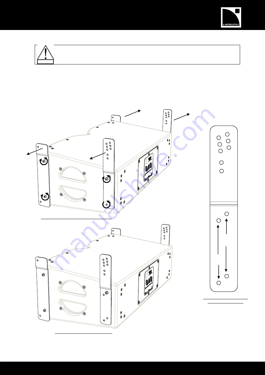
Mount four arms to a first KARAi (hereafter designated as KARAi#1) as follows (repeat on each enclosure side):
The four arms are different and can be identified by a number engraved on each of them. Mount
arm 641 on the rear left, 642 on the front left, 801 on the front right, and 802 on the rear right.
Orient the top part of each arm outwards.
a.
Undo both front 55 mm Torx
®
screws (T30 bit).
b.
Position the appropriate front arm and slightly drive both preceding screws.
c.
Undo both rear 55 mm Torx
®
screws (T30 bit).
d.
Position the appropriate angle arm and slightly drive the top rear screw only. The position of the arm
depends on the angle intended to be set, as shown in Figure 6. Note: It is recommended to select the 10°
angle on the KARAi intended to be fixed to the M-BUMPi. In that way, the KARAi axis will be parallel to the
M-BUMPi.
Figure 6: Mounting four arms to a KARAi
0°
2°
4°
7.5°
10°
1°
3°
5°
Screw holes for angles
0°/2°/4°/7.5°/10°
Screw holes for
angles 1°/3°/5°
KARAi assembled for angles 1°/3°/5°
KARAi assembled for angles 0°/2°/4°/7.5°/10°
Angle arm detail with inter-
enclosures angle holes
Arm 642
Arm 641
Arm 801
Arm 802
Top part
oriented
outwards
a.
b.
a.
b.
c.
d.
c.
WARNING
Summary of Contents for KARAi
Page 1: ...KARAi rigging manual EN ...


