


12XT_UM_ML_1-3
w w w . l - a c o u s t i c s . c o m
19
19
19
19 en
EN
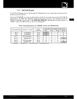
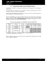
Table 5: Accessible parameters in ‘‘FULL RANGE’’ mode for the ACTIVE 12XT
Accessible (O) and blocked (X) parameters
LA4 Inputs/
Outputs
Elements
to connect
Preset
assignments*
Mute
Gain
Delay
Polarity
IN A
Input signal A
IN_A
X
O
O
O
IN B
Input signal B
IN_B
X
O
O
O
OUT 1
ACTIVE 12XT
LF_A
O
X**
X
X
OUT 2
HF_A
O
X
X
X
OUT 3
ACTIVE 12XT
LF_B
O
X**
X
X
OUT 4
HF_B
O
X
X
X
* IN: input signal. A, B: channel A, B. LF: low frequency transducer. HF: high frequency transducer.
** Both LF gains are unlocked for the [12XTA_MO] preset.
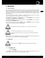
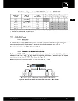
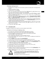
7.3.2
“HIGH-PASS” mode
7.3.2.1
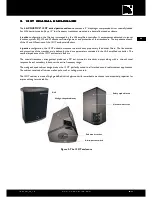
Description
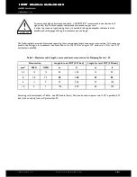
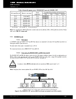
In ‘‘HIGH-PASS’’ mode the ACTIVE 12XT enclosures are 100 Hz high-pass filtered to allow using them along with the
dedicated complimentary SB118 subwoofers. The bandwidth of the system is extended down to 32 Hz.
The recommended ratio is one ACTIVE 12XT for one SB118.
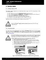
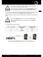
7.3.2.2
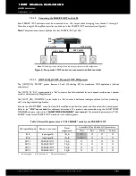
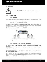
Connecting the ACTIVE 12XT to the LA4
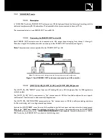
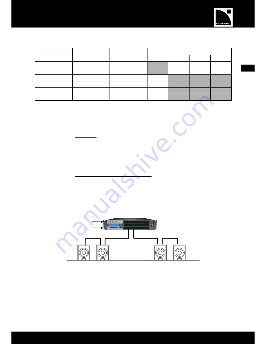
The first two ACTIVE 12XT enclosures are connected to the output channels 1 and 3 of the LA4 controller. An
additional ACTIVE 12XT enclosure can be connected in parallel with each first one. Therefore a single LA4 amplified
controller can drive up to four ACTIVE 12XT enclosures (see Figure 10).
Note:
The system resources are optimized for two or four ACTIVE 12XT per LA4.
Figure 10: Four ACTIVE 12XT enclosures connected to an LA4 controller
IN A
IN B
Note:
This drawing is only a cabling scheme and does not represent a valid configuration.
OUT 1 (IN A)
OUT 3 (IN B)
Summary of Contents for 12XT
Page 2: ...w w w l a c o u s t i c s c o m ...
Page 28: ...w w w l a c o u s t i c s c o m ...
Page 54: ...w w w l a c o u s t i c s c o m ...


