Instruction manual
INSULATION - CONTINUITY TESTER
KEW 3021 3022 3023
KYORITSU ELECTRICAL INSTRUMENTS
WORKS,LTD.
Page 1: ...Instruction manual INSULATION CONTINUITY TESTER KEW 3021 3022 3023 KYORITSU ELECTRICAL INSTRUMENTS WORKS LTD ...
Page 2: ... 6 4 Output voltage characteristics 13 6 5 Measurement of resistance Continuity check 14 6 6 Backlight function 15 6 7 Auto power off 15 7 Functions keys 16 7 1 Comparator function 16 7 2 Memory save function 17 8 Fuse Battery replacement 18 8 1 Battery replacement 18 8 2 Fuse replacement 18 9 Notes on Housing case and accessories 19 9 1 Case lid 19 9 2 Neck strap and Cord case 19 9 3 Test prods a...
Page 3: ...age to equipment under test The symbol indicated on the instrument means that the user must refer to the related parts in the manual for safe operation of the instrument It is essential to read the instructions wherever the symbol appears in the manual DANGER is reserved for conditions and actions that are likely to cause serious or fatal injury WARNING is reserved for conditions and actions that ...
Page 4: ...rument is wet Ensure that the test leads are firmly inserted into the terminal Set the Range selector switch to OFF position when opening the Battery cover for battery replacement CAUTION Always set the Range selector switch to the appropriate position before making measurement Set the Range selector switch to OFF position after use and remove the test leads The instrument consume small current at...
Page 5: ...value is held for about 5 sec after insulation resistance measurement of the Test button is released Backlight function to facilitate work at night or dimly lit locations Bar graph to indicate measured results Max 99 data can be saved to the internal memory at the insulation resistance range Visible and audible warning or is indicated and buzzer sounds when the measured insulation resistance excee...
Page 6: ...1001 2000MΩ 200 1 2000MΩ 40 0 2000MΩ 20 01 200 0MΩ 0 0 099MΩ 0 0 099MΩ 0 0 099MΩ 2 rdg 6dgt 5 rdg 6dgt Within 6dgt 50MΩ 5MΩ 5MΩ 0 100 200 0MΩ 0 100 40 0MΩ 0 100 20 0MΩ 0 5MΩ 0 25MΩ 0 125MΩ 500V 250V 125V 0 4 40 200MΩ Nominal voltage Auto Range Open circuit voltage Short circuit current Nominal test current 1st effective measurement range Center scale range Accuracy 2nd effective measurement range ...
Page 7: ... 0MΩ 0 5MΩ 0 25MΩ 0 1MΩ 500V 250V 100V 0 4 40 200MΩ Operating error Operating error B is an error obtained under the nominal operating conditions and calculated with the intrinsic error A which is an error of the instrument used and the error En due to variations According to IEC61557 the maximum operating error should be within 30 B A 1 15 E1 2 E2 2 E3 2 A Intrinsic error B Operating error E1 Var...
Page 8: ...ical circuit and the enclosure Overload protection The instrument operates properly after each of the voltage shown in the table below is applied for 10 sec 20 600V 3 rdg 6dgt Within 6dgt Measured voltage Accuracy Accuracy at 0 Auto range Open circuit voltage DC Short circuit current Measuring range to keep operating error tolerance Outside of the measuring range to keep operating error tolerance ...
Page 9: ...o less than 320 Dimension approx 105 L 158 W 70 D mm Weight approx 600g including batteries Power source R6P or LR6 size AA x 6pcs Nominal power 2 7VA Accessories MODEL7103 Test lead with remote control switch 1 set MODEL7161 test bar 1 pce MODEL7131 Safety alligator clip 1 pce MODEL8017 Extension prod 1 pce Neck strap 1 pce Cord cas 1 pce R6P SUM 3 size AA 6 pcs Instruction manual 1 pce Optional ...
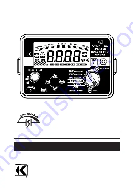
Page 10: ...probe Standard prod MODEL8072 Probe connector Safety alligator clip MODEL7131 Range selector switch MEM key UP key 0ΩADJ key Backlight key Display Test lead with remote control switch MODEL7103 Remote control switch Earth code Test bar MODEL7161 Extension prod MODEL8017 22 Fig 2 Instrument layout KEW3022 ...
Page 11: ...acing the fuse In this case send the instrument to your local KYORITSU distributor for repair DANGER When the Test button or the Remote control switch is pressed while the Range selector switch set to an insulation resistance range take care not to touch the tip of the Test probe where a high voltage is present in order to avoid possible shock hazard Test lead and fuse must be inspected prior to m...
Page 12: ...le electrical shock hazard Voltage cannot be measured if a break is present on the fuse Never make measurement on a circuit in which the electrical potential exceeds AC DC600V in order to avoid possible shock hazard Refer to 3 Specification AC voltage measurement When testing installation that has a large current capacity such as a power line be sure to make measurement on the secondary side of a ...
Page 13: ...NGER When the Test button or Remote control switch is pressed with the Range selector switch set to an insulation resistance range position take care not to touch the tip of the test probe or the circuit under test where a high voltage is present in order to avoid possible shock hazard Do not make measurement with the Battery cover removed CAUTION Ensure that the circuit under test is de energized...
Page 14: ...witch to the OFF position or turn the Remote control switch off with the test lead connected Discharge can be monitored by the LIVE LED and mark 2 Connect the Earth probe to the earth terminal of the circuit under test If the circuit is not earthed connect the Earth probe to any appropriate conductor 3 Connect the Line probe to the circuit under test and press the Test button or Remote control swi...
Page 15: ...esent at the tip of a probe Attention should be paid to avoid possible shock hazard 6 4 Output voltage characteristics This instrument conforms to IEC61557 This standard defines that the nominal current shall be at least 1mA and the lower limit of the insulation resistance maintaining the nominal voltage at the measurement terminal See the graph below This value is calculated by dividing the nomin...
Page 16: ...lead or fuse in order to display the resistance of the equipment under test only Setting 1 Set the Range selector switch to theΩ Continuity position 2 Short the test leads LINE red and EARTH black 3 Press the Zero Ω ADJ key with the Test button locked or with the Remote control switch pressed Then mark is lit up and a value of 0 00 Ω is displayed on the LCD This value is saved in the memory of the...
Page 17: ...and EARTH black are shorted Change the connection of LINE red and EARTH black when measuring the voltage with the switched polarities The measurement result at the resistance function may be effected by the impedance or transient current in the operating circuit which is connected in parallel to the instrument 6 6 Backlight function To facilitate working in dimly lit situations a backlight functio...
Page 18: ...0V range 2 Press the UP or DOWN key to select or and then press the key Select to sound the when the measured value exceeds the pre set value Select to sound the when the measured value is under the pre set value 3 The number displayed at the lower left on the LCD starts flickering Press the UP or DOWN key to select the reference value and press the key 4 The message and the set value are displaye...
Page 19: ...ta 1 Set the Range selector switch to any desired Insulation resistance range and press the key 2 Press the UP or DOWN key to switch the memory number The measured voltage and value are displayed on the LCD Deleting all memory data 1 To delete all memory rotate the Range selector switch from OFF to Ω CONTINUITY position with the key pressed down Then release the key 2 The message clr is displayed ...
Page 20: ...he test probe from the instrument 2 Open the battery compartment cover by unscrewing the metal captive screw to reveal battery compartment 3 Always replace all six batteries with new ones at the same time 4 Screw the battery compartment lid back on before using the instrument 8 2 Fuse Replacement 1 Disconnect the test probe from the instrument 2 Open the battery compartment cover by unscrewing the...
Page 21: ... 2 Turn it 180 degrees Put the Case lid under the Housing case 3 Hook it on to the Housing case 9 2 Neck strap and Cord case This instrument is equipped with a strap to suspend from the neck to allow both hands to be used freely for easy and safe operation 19 9 Notes on Housing case and accessories Fig 14 Fig 15 ...
Page 22: ...rod Used for ordinary measurement Attached to the Line probe at the time of purchase MODEL8017 Extension probe Used in difficult to reach situations MODEL8016 Pickle prod Optional Used to hook the probe on a conductor 2 How to replace Test prod To remove the Test prod turn the cap of LINE probe counterclockwise Insert the threaded end of another prod into the hexagonal hole on the probe cap as sho...
Page 23: ...nic solvent such as benzene acetone etc 10 Cleaning of the instrument If this tester should fail to operate correctly return it to your nearest distributors stating the exact nature of the fault Before returning the instrument make sure that a Operating instructions have been followed b Test Leads have been inspected c Fuse has been checked d Battery has been checked e The unit is returned with al...
Page 24: ...U ELECTRICAL INSTRUMENTS WORKS LTD No 5 20 Nakane 2 chome Meguro ku Tokyo 152 0031 Japan Phone 81 3 3723 0131 Fax 81 3 3723 0152 URL http www kew ltd co jp E mail info kew ltd co jp Factories Uwajima Ehime 04 12 92 1635A ...