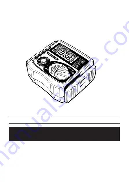
MODEL 4116A, 4118A, 4120A
DIGITAL PSC-LOOP TESTER
INSTRUCTION MANUAL
KYORITSU ELECTRICAL INSTRUMENTS
WORKS,LTD.
Page 1: ...MODEL 4116A 4118A 4120A DIGITAL PSC LOOP TESTER INSTRUCTION MANUAL KYORITSU ELECTRICAL INSTRUMENTS WORKS LTD...
Page 2: ...1 Initial Checks 8 5 2 Measurement of the Loop Impedance 9 5 3 Measurement of Prospective Short Circuit Current 10 6 DETAILED EXPLANATION 10 6 1 Measurement of Fault Loop Impedance and Prospective Fau...
Page 3: ...e instructions KYORITSU will not accept liability for any damage or injury caused by misuse or non compliance with the instructions or with the safety procedures 2 It is essential to read and to under...
Page 4: ...splay disconnect the instrument from the mains supply and allow to cool down If abnormal conditions of any sort are noted such as a faulty display unexpected readings broken case cracked test leads et...
Page 5: ...otect against an impact from the outside and prevent the operation part the LCD and the connector socket from becoming dirty The cover can be detached and put on the back side of the main body during...
Page 6: ...nector Fig 3 DANGER Use original test lead only Max allowed voltage between mains test terminals and ground is 300V This instrument is intended only for use in single phase operation at 230V 10 15 AC...
Page 7: ...ot operate on the Loop 2000 Mains voltage with which D LOK operates is as shown in the table below 3 3 2 Applied Standards Instrument operation IEC EN 61557 1 IEC61557 3 Safety IEC EN 61010 1 CAT 300V...
Page 8: ...ge measurement is carried out with low test current 15mA The current will not cause tripping out involved RCD even the one with the lowest nominal differential current 30mA Display The liquid crystal...
Page 9: ...humidity 75 or less no condensation Symbols used on the Equipment protected throughout by DOUBLE INSULATION or REINFORCED INSULATION Caution refer to accompanying instruction manual and humidity and...
Page 10: ...be OFF CAUTION Always inspect your test instrument and lead accessories for abnormality or damage If abnormal conditions exist DO NOT PROCEED WITH TESTING Lead Plug Fig 5 Operating Error of Loop Impe...
Page 11: ...voltage if required 6 Press the Press to Test button The value of loop impedance will be displayed with the appropriate units A bleep will sound on completion of the test For best results always test...
Page 12: ...56 0A To hold the reading keep the button held down or turn clockwise to lock for Auto Test Note For loop impedance greater than 210 on PSC 200A range and 25 on 2000A 20kA ranges the fault voltage ma...
Page 13: ...following partial impedances Impedance of power transformer s secondary Phase conductor resistance from power transformer to fault location Protection conductor resistance from fault location to loca...
Page 14: ...5 s When the protection device is a residual current device RCD Ia is the rated residual operating current I n For instance in a TT system protected by a RCD the max RA values are Note The loop teste...
Page 15: ...ndition shall be fulfilled for each circuit Zs Uo Ia Where Zs is the Fault loop impedance Uo is the nominal voltage between phase to earth Ia is the current causing the automatic disconnection of the...
Page 16: ...her than Ia of the protective device concerned Practical example of verification of the protection in a TN system according to the international Standard IEC 60364 Fig 9 Rating A Disconnecting time 5s...
Page 17: ...to earth of 127 V instead of 230V and normally the neutral conductor is not used Connecting the loop testers to this system all three wiring check LEDs should be lit and the display reads a value of 1...
Page 18: ...ld be higher than Prospective Short Circuit current otherwise it is necessary to change the rated current of involved over current protection device Practical example of line impedance test and prospe...
Page 19: ...ument is intended only for use in single phase operation at 230V 10 15 AC phase to earth or for use in OLD TT system phase to neutral If the overheat symbol appears in the display disconnect the instr...
Page 20: ...01 05 92 1483 DISTRIBUTOR Kyoritsu reserves the rights to change specifications or designs described in this manual without notice and without obligations...