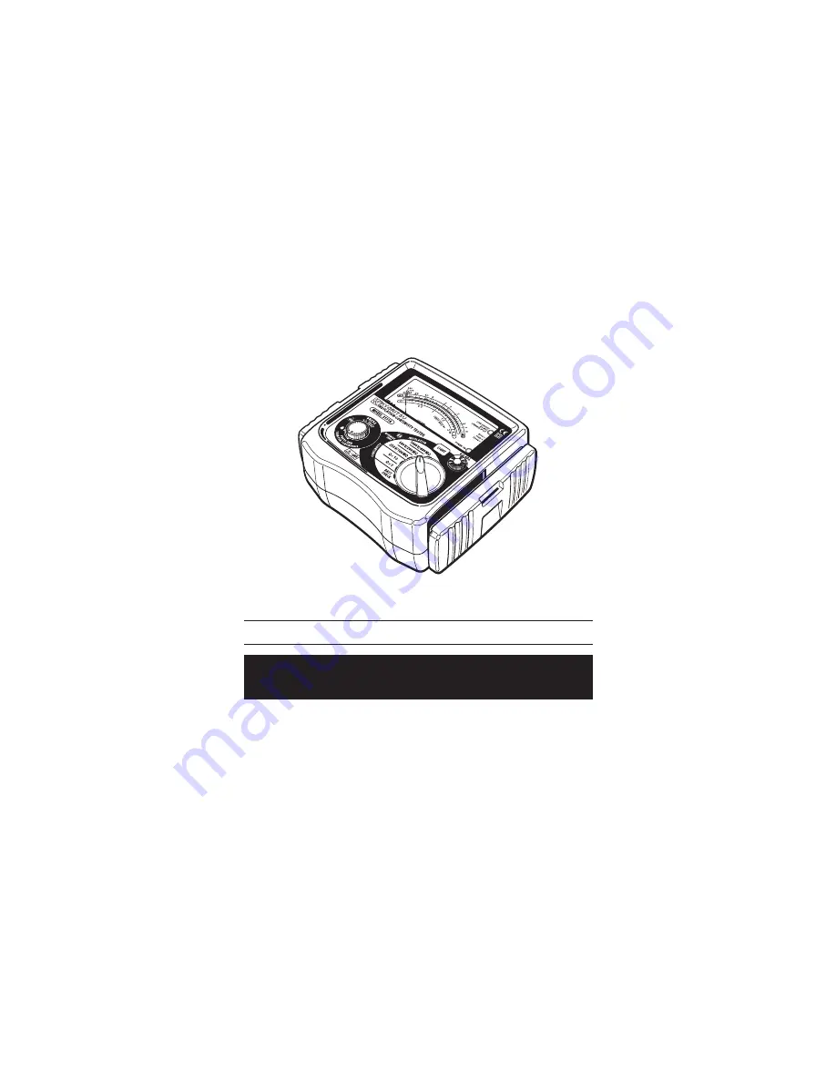
MODEL 3131A
ANALOGUE INSULATION/CONTINUITY TESTER
INSTRUCTION MANUAL
www.
GlobalTestSupply
.com
Find Quality Products Online at:
[email protected]
Page 1: ...MODEL 3131A ANALOGUE INSULATION CONTINUITY TESTER INSTRUCTION MANUAL www GlobalTestSupply com Find Quality Products Online at sales GlobalTestSupply com...
Page 2: ...ection and Check of Power Source of Circuit Under Test 12 6 2 Insulation Resistance Measurement 13 6 3 Continuity Testing Resistance Tests 14 6 4 Continuous Measurement 15 7 Back Light Function 16 8 B...
Page 3: ...instructions contained in the manual It is essential that the above instructions are adhered to Failure to follow the above instructions may cause injury instrument damage and or damage to equipment u...
Page 4: ...wise the use of the instrument may cause sparking which can lead to an explosion Do not make measurement when thunder is rumbling If the instrument is in use stop the measurement immediately and remov...
Page 5: ...connect the test probe from the instrument before opening the battery compartment cover for battery and fuse replacement Stop using the test lead if the outer jacket is damaged and the inner metal or...
Page 6: ...signed for CAT II O Circuits which are not directly connected to the mains power supply CAT II Primary electrical circuits of equipment connected to an AC electrical outlet by a power cord CAT III Pri...
Page 7: ...ranges 250V 100M 500V 200M 1000V 400M Two continuity test ranges 2 20 Back light function to facilitate work at night or dimly lit locations Easy for battery check Power on indication LED lighting du...
Page 8: ...rent Accuracy Zero Adjustment Range 4 9V DC 200mA DC min 3 of scale length 0 2 min Ranges 250V 100M 500V 200M 1000V 400M Measuring range to keep operating instrumetal uncertainty Maximum percentage op...
Page 9: ...0 relative humidity up to 85 Storage Temperature Humidity 20 60 relative humidity up to 85 Insulation Resistance More than 50M at 1000V DC between electrical circuit and housing case Withstand Voltage...
Page 10: ...NING LED POWER ON INDICATION LED CONTINUITY ZERO ADJUST LIGHT SWITCH RANGE SELECTOR SWITCH TEST PROBE RED LINE PROBE TEST PROBE BLACK EARTH PROBE ALLIGATOR CLIP BLACK PROTECTIVE FIGERGUARD Fig 1 Part...
Page 11: ...g the minimum required air and creepage distances Cap Uncapped condition for CAT II environment Capped condition for CAT III IV environments The Cap shuld be firmly attached to the probes Protective n...
Page 12: ...side and prevent the operation part and the connector socket from becoming dirty Remove the cover and put it on the back side of the main body to make measurements 5 1 1 Method of removing the cover 5...
Page 13: ...acement 5 4 Test Probe Connection Insert the test probe fully into the terminal of the instrument Connect the earth clip of the test probe black to EARTH terminal and the line probe red to LINE termin...
Page 14: ...s may damage the circuit Voltage check can be made with the range selector switch at any position Be sure to turn off the breaker for the circuit under test Connect the earth clip of the test probe bl...
Page 15: ...rguard on test probe to avoid the possible shock hazard CAUTION Never press the test button if the live circuit warning LED is lit or the warning buzzer sounds This may damage the circuit Conduct the...
Page 16: ...it under test is de energized In case that an additional operating circuit is connected in parallel to the circuit under measurement the measurement error might be caused due to the effects of impedan...
Page 17: ...value can be obtained by applying a certain current to the resistance under test and measuring the voltage generated on the both sides of the resistance under test Resistance Value Voltage Current RX...
Page 18: ...light button must be pressed and released while pressing the test button The back light continues illuminating for approx 40 seconds and then turn off automatically When the test button is released th...
Page 19: ...rewing the metal captive screw to reveal battery compartment and replace the fuse Fuse type F500mA 600V fast acting ceramic fuse 6 35 x 32mm Install batteries in correct polarity as marked inside the...
Page 20: ...und the neck both hands can be used freely for easy and safety working How to fit the strap belt Whole diagram when the test probe pouch is attached Fig 9 How to fit the strap belt Fig 10 How to fit t...
Page 21: ...make measurement When static electricity builds up on the meter cover and affects the meter reading use a cloth dampened with off the shelf anti static agent or detergent to wipe the meter cover surf...