Kyocera FS-1050 - B/W Laser Printer Service Manual Download Page 9

6-3

FS-1050

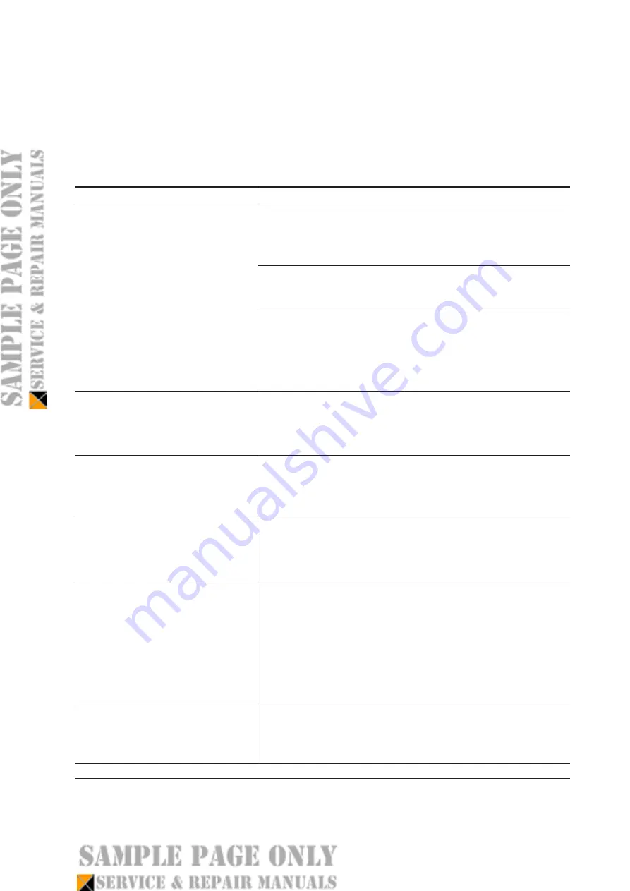
6-1 Troubleshooting

6-1-1 General error handling

(1) Maintenance messages

Message

Corrective action

The 

ATTENTION

 indicator flashes. Indicates that paper has

run out. Supply paper according to the paper source (Cassette

or MP tray) and paper size (A4, B5, A5, etc.) displayed.

The paper cassette is not properly closed. Make sure the paper

cassette is closed securely.

The 

ATTENTION

  indicator turns on and the 

READY

indicator goes off. Indicates a problem with the controller

and the operator panel. Call a service person. The printer

does not operate when this message is displayed.

The 

ATTENTION

 indicator turns on. Indicates a controller

error. Call a service person. The printer does not operate

when this message is displayed.

The 

ATTENTION

 indicator turns on. Indicates a mechanical

error. Call a service person. 0123456 indicates the number

of printed pages.

The 

ATTENTION

  indicator turns on. The waste toner

reservoir is full. 0123456 indicates the number of printed

pages. (See page 6-7)

The 

ATTENTION

  indicator turns on and the 

READY

indicator flashes. Indicates that the cassette and data paper

sizes do not match. The printer feeds from the MP tray when

the paper in the cassette is of a different size than that of the

print data. Put paper of the correct size in the MP tray then

press the 

GO


key to resume printing.

The 

ATTENTION

 indicator flashes. Indicates that a failure

has occurred with the optional network interface board.

Check the optional interface installed in the printer.

Add paper (paper source)

(size)

Call service

person F0

Call service

####

Call service

####:0123456

Call service

7980:0123456

Load MP tray

(paper size)

Option Interface

Error          ##

Summary of Contents for FS-1050 - B/W Laser Printer

Page 1: ...SERVICE MANUAL Published in Dec 01 Laser printer ...

Page 2: ...3 Using the operator panel 2 15 Chapter 3 3 1 Maintenance Adjustments 3 3 Chapter 4 4 1 Electrophotographic system 4 3 4 2 Paper feeding system 4 15 4 3 Electrical control system 4 18 Chapter 5 5 1 General instructions 5 3 5 2 Disassembly 5 4 Chapter 6 6 1 Troubleshooting 6 3 Appendix A Timing charts A 3 Wiring diagram A 9 Appendix B Status page B 3 Appendix C Parallel interface C 3 USB interface ...

Page 3: ... Laser safety 1 7 2 Laser notice 1 7 3 Laser caution label on the scanner unit 1 7 4 CDRH regulations U S A 1 9 5 Ozone concentration 1 9 6 Optional equipment 1 9 7 Important note on the interface connectors 1 9 1 4 Environmental requirements 1 10 1 4 1 Environmental conditions 1 10 1 Clearance 1 11 2 Places to avoid 1 12 3 Note on power 1 12 4 Removing the printer 1 13 1 5 About the toner contain...

Page 4: ... 2 8 3 Notes on handling DIMM 2 9 4 Installing the DIMM 2 10 5 Testing the expansion memory 2 11 5 Installing the memory card CompactFlash 2 12 6 Installing the network interface card 2 14 2 3 Using the operator panel 2 15 2 3 1 Operator panel 2 15 1 LED Indicators 2 15 2 keys 2 16 3 LCD message display 2 17 Interface indicator 2 18 Paper size indicator 2 18 2 3 2 Menu selection system 2 19 1 Menu...

Page 5: ...ainer 3 4 3 Toner container replacement 3 5 4 Toner saver mode EcoPrint 3 6 3 1 3 Cleaning the printer 3 7 1 Cleaning the registration roller 3 8 2 Cleaning the main charger wire 3 8 3 1 4 Updating the firmware 3 9 1 Firmware program data format 3 9 2 Downloading the firmware from the parallel interface 3 10 3 Downloading the firmware from the memory card 3 12 4 Downloading errors 3 14 ...

Page 6: ...0 4 Transfer 4 11 5 Fusing 4 12 Fuser unit mechanism 4 13 6 Cleaning 4 14 4 2 Paper feeding system 4 15 4 2 1 Paper feed control 4 16 Paper feeding mechanism 4 17 4 3 Electrical control system 4 18 4 3 1 Electrical parts layout 4 18 4 3 2 Operation of circuit boards 4 19 1 Main board 4 19 2 Engine board 4 20 Eraser lamp control circuit 4 21 Polygon motor control circuit 4 25 3 Power supply board 4...

Page 7: ...ransfer roller 5 10 5 2 6 Removing the principal circuit boards 5 11 1 Removing the engine board 5 11 2 Removing the main board 5 12 3 Removing the power supply board and high voltage board 5 14 4 Removing the bias board 5 15 5 2 7 Removing the main motor and drive unit 5 16 5 2 8 Removing and splitting the fuser unit 5 20 1 Removing the separators 5 22 2 Removing the heater lamp 5 23 3 Removing t...

Page 8: ...r scanner unit Pin photo diode error 6 12 6 Call service 6110 Fuser unit error 6 14 7 Call service 5300 Eraser lamp error 6 15 8 Call service F010 Controller checksum error 6 16 9 Call service F020 Controller RAM read write error 6 16 6 1 3 Print quality problems 6 17 1 Completely blank printout 6 18 2 All black printout 6 19 3 Dropouts 6 20 4 Black dots 6 21 5 Black horizontal streaks 6 21 6 Blac...

Page 9: ...played The ATTENTION indicator turns on Indicates a mechanical error Call a service person 0123456 indicates the number of printed pages The ATTENTION indicator turns on The waste toner reservoir is full 0123456 indicates the number of printed pages See page 6 7 The ATTENTION indicator turns on and the READY indicator flashes Indicates that the cassette and data paper sizes do not match The printe...

Page 10: ...Published in Oct 2001 FS105070770 842FS1050120 FS 1050 Laser Printer PARTS LIST ...

Page 11: ...FS 1050 3 1 Enclosure 0A02 0032 0002 0003 0010 0011 0012 0006 0038 0007 G101 G002 G002 0008 0005 0024 0022 0004 0023 G003 0036 0030 0031 0031 0037 0037 0035 0026 Since April 2001 Until March 2001 ...

Reviews: