background image

8—Connect the Printer to the Computer

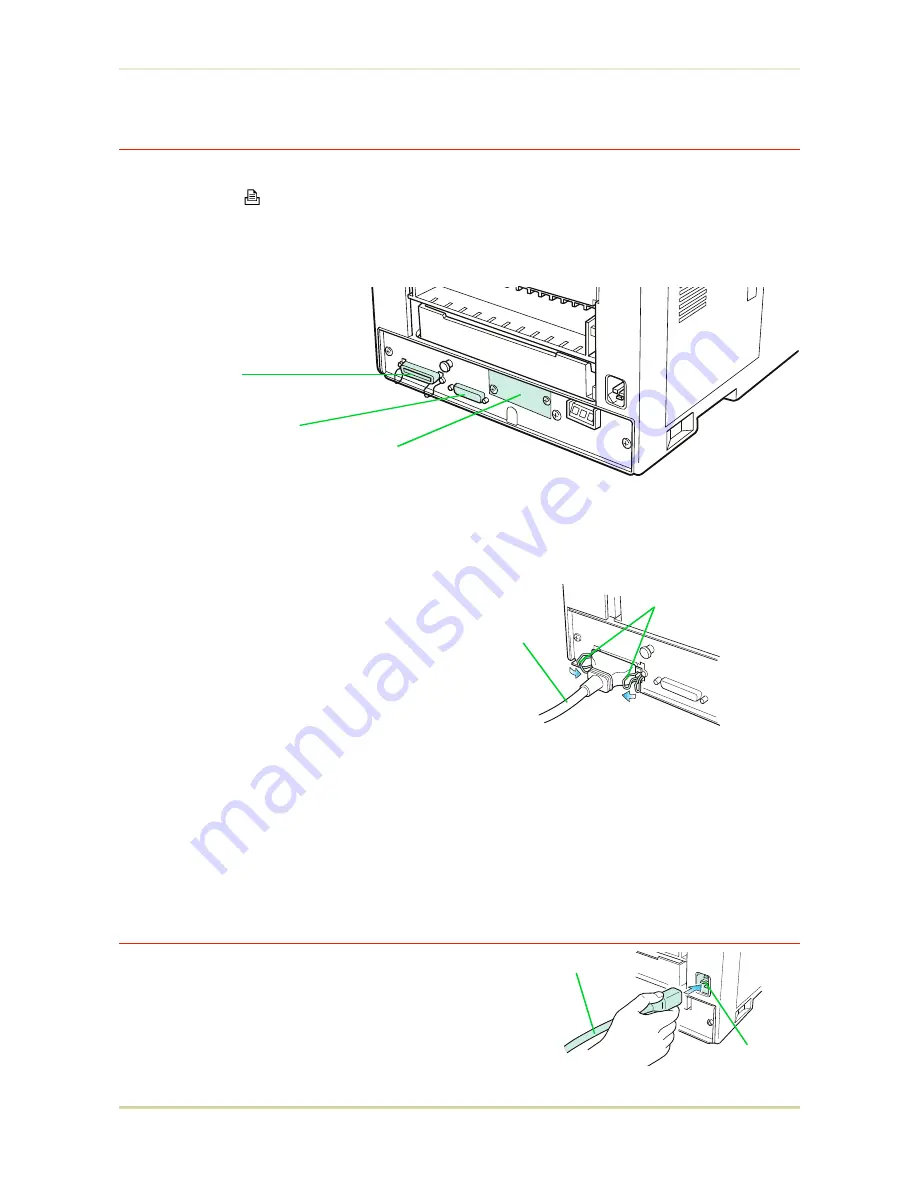
The printer has two computer cable connectors and a slot for installing an option interface.
The one marked "  " is for a parallel (Centronics standard) interface. The one marked "

I

š

I

š

I

"

is for a serial (RS-232C/RS-422A) interface. You may use whichever is convenient for your com-
puter, with the option interface, if you have already have one installed. All interface connec-
tors can be used simultaneously with different computers.

*

Only connect or disconnect cables to the connectors while the printer and
computer power are switched off.

Parallel interface

Plug one end of the cable into the connector
marked 

Parallel 

on the printer. Close the clips

on both sides to hold it in place.

Plug the other end into a parallel (Centronics)
interface connector on your computer. This
connector is usually marked 

PRINTER

.

See 

Appendix C

 for more details about the par-

allel interface.

Serial interface

The serial interface of this printer is set to RS-232C mode before leaving the factory, but can
also be set to RS-422A mode to suit your operating environment. Follow the instructions in

Appendix C

9—Attach the Power Cord

1.

Check that the power switch is off.

2.

Plug one end of the power cord into the receptacle
at the back of the printer.

3.

Plug the other end into the wall outlet.

Clips

Rear Panel

Printer Cable

Parallel Interface
Connector

Serial (RS-232C/RS-422A)
Interface Connector

Option Interface
Slot Cover

Power Cord
Receptacle

Power Cord

1.4. Setting Up and Interfacing

1-13

Summary of Contents for FS-3700

Page 1: ...ace of 92 cm by 61 cm by 138 cm 36 by 24 by 54 inches is needed Places to Avoid Avoid installing the printer in locations subject to pDirect drafts of hot or cold air pDirect drafts from outside Avoid locations near doors leading outside pSudden temperature or humidity changes pSources of high temperature for example near stoves or radiators pExcessive dust 30 cm 12 inches 40 cm 16 inches 20 cm 8 ...

Page 2: ... an AC wall outlet preferably one that can be used for the printer alone see sec tion Power Supply on next page Power requirements are Voltage 120 V U S A Canada 220 V to 240 V European countries 10 at each voltage Frequency 60 Hz 120 V 2 50 Hz 220 V to 240 V 2 Current capacity FS 1700 Max 5 8 A at 120 V or Max 3 A at 220 V to 240 V FS 3700 Max 7 8 A at 120 V or Max 4 A at 220 V to 240 V The outle...

Page 3: ...or any signs of damage that may have been caused during transporta tion If the carton is found to be badly damaged leave the carton unopened and immediately notify the dealer from whom you purchased the printer Save the box and other packing materials in case you have to repack the printer for transporta tion at a later date As the disconnect device is not incorporated in the printer s AC primary ...

Page 4: ...anual this booklet E Face up output tray F Power cord To remove the printer from the box grasp the handholds on either side of the printer Lift the printer from the carton as shown below u Always use these handholds whenever you lift or move the printer u The handhold on the right side of the printer doubles as the memory card slot Be sure to remove the memory card first if inserted before lifting...

Page 5: ...e used throughout this manual Front View Memory Card Slot Transfer Roller Registration Roller Paper Feed Unit Multi Purpose Tray Paper Cassette Control Panel Multi Purpose Tray Paper Feed Unit Release Lever Paper Cassette Side Cover Power Switch Face down Output Tray Paper Stopper Paper Full Sensor Model FS 3700 only 1 3 Names of Parts 1 5 ...

Page 6: ...or Parallel Interface Connector Option Interface Slot Cover To protect the printer against static discharge the connector must be covered with the supplied protective cap when not in use Toner Container Release Lever Green Toner Container Top Cover Side Cover Waste Toner Bottle Cleaner Knob Green Main Charger Unit 1 3 Names of Parts 1 6 ...

Page 7: ...en the top cover 2 Install the toner container 3 Close the top cover 4 Install the waste toner bottle 5 Add paper 6 Open the paper stopper on the face down output tray 7 Install the face up output tray if required 8 Connect the printer to the computer 9 Attach the power cord 10 Print a status page 11 Test the interface with the computer 12 Set the emulation mode 13 Install the printer driver 1 4 S...

Page 8: ...imes or more to loosen and mix the toner inside 3 The bottom of the toner container is sealed with a sealing strip Peel off the seal on the toner container and carefully pull off and dis pose of the sealing strip Be sure to peel the seal off the toner container before the toner container is fitted into the developer unit 4 Install the toner container on the developer as show in the diagram Top Cov...

Page 9: ... cover by pressing the arrowed part in this diagram 4 Install the Waste Toner Bottle The waste toner bottle is in the toner kit supplied with the printer The waste toner bottle must be installed in the printer Install the waste toner bottle in the printer as follows 1 Take the waste toner bottle from the toner kit supplied Do not cap the waste toner bottle Top Cover Top Cover Waste Toner Bottle Ca...

Page 10: ...of the printer 3 Insert the waste toner bottle with the bottle tilted slightly towards you as shown in the figure 4 Ensuring that it is correctly inserted close the side cover Waste Toner Bottle Side Cover 1 4 Setting Up and Interfacing 1 10 ...

Page 11: ...t put in more paper than the limit indi cated on the cassette The cassette should hold approximately 250 sheets of paper with a 75 g m2 20 lb ream basis weight 0 1 mm thickness 2 Set the clips at the two corners as shown right Some types of paper such as thick paper may be hard to place in the cassette using this method If this is the case the process is facilitated by inserting the paper from the...

Page 12: ...uired If you want the printed pages stacked face up in reverse order mount the face up output tray as follows Depending on the size of the paper you use mount the paper stopper on the face up output tray as shown below Paper Stopper Face up Output Tray Legal Size A4 Size Letter Size Paper Stopper 1 4 Setting Up and Interfacing 1 12 ...

Page 13: ... the printer Close the clips on both sides to hold it in place Plug the other end into a parallel Centronics interface connector on your computer This connector is usually marked PRINTER See Appendix C for more details about the par allel interface Serial interface The serial interface of this printer is set to RS 232C mode before leaving the factory but can also be set to RS 422A mode to suit you...

Page 14: ...low 1 Check that the printer s message display indicates Ready and that the ON LINE indica tor is ON 2 Boot the computer in DOS mode or set the computer to DOS prompt MODE 3 At the DOS prompt type the following ECHO R STAT EXIT PRN If the printer prints a status page the computer and printer are connected correctly For details on the status page refer to Chapter 2 If you do not get this result che...

Page 15: ...with Win dows 3 1 or Windows 95 To print with a Macintosh computer you must purchase an IB 3 AppleTalk in terface kit and a KPDL PostScript Printer Upgrade Kit To install the printer driver proceed as follows Reference to the Windows manual is also rec ommended Windows 95 1 Click the Start button point to Settings and then Printers 2 Double click Add Printer 3 Add Printer Wizard will be shown Foll...

Page 16: ...ontrol Panel 4 Double click on Printers 5 Click on Add 6 Click on Install 7 Select Install Unlisted or Updated Printer under List of Printers 8 Click Install 9 Select the drive into which you inserted the Kyocera Digital Library CD ROM and follow the instructions that appear on the screen 10 When the driver is installed click on Close to close Control Panel 1 4 Setting Up and Interfacing 1 16 ...

Page 17: ...ray is of A4 size 21 x 29 7 cm if the MP tray setting is at A4 or smaller and the multi purpose tray mode is Cassette Otherwise the printer assumes the paper size is of legal size To avoid paper jam do not put legal size paper in the multi purpose tray if the MP Tray setting is at A4 or smaller and the multi purpose tray mode is Cassette Selecting the Multi Purpose Tray 1 Taking hold of the front ...

Page 18: ...man ual mode see page 1 19 and print out one sheet at a time The following pages explain the use of the multi purpose tray in the Cassette Mode Manual Mode and First Mode Cassette mode 1 Press the MODE key to display MP tray mode 2 After pressing the ENTER key the mode display is changed by pressing the and keys Use these keys to display Cassette and then press the ENTER key MP tray mode Cassette ...

Page 19: ...ata from the computer The printer indicates Processing after which the message Set paper Press CONT will be displayed If you want to abandon the manual feeding procedure press the CANCEL key The mes sage display indicates Print Cancel Press the ENTER key The printer will re turn to Ready 7 Press the CONT key and printing will begin 8 If printing is to be continued press the CONT key when the messa...

Page 20: ...s above even while the printer is presently feeding the paper in the printer s cassette 1 Press the MODE key to display MP tray mode 2 After pressing the ENTER key the mode display is changed by pressing the and keys Use these keys to display First and then press the ENTER key MP tray mode First 3 Press the EXIT key u The printer will not switch to light the multi purpose tray indicator while the ...

Page 21: ...y card 1 Switch printer power off Do not insert or remove a memory card while power is on If the memory card is removed while the printer is on damage could result in the printer s electronics or the memory card 2 Insert the memory card in the slot Insert it face up connector end first Push it in all the way 3 Switch printer power on The printer reads the contents of the memory card during its pow...

Page 22: ...force a memory card into its slot pNever bend a memory card pAvoid impact Do not drop a memory card pDo not touch the terminals of the memory card pDo not spill water or other liquids on a memory card pKeep memory cards away from naked flames and other sources of heat pDo not leave memory cards lying in direct sunlight For details regarding the use of the memory card refer to the User s Manual sec...

Page 23: ...ion 300 dpi 600 dpi HP LaserJet 4 Plus only 2 MB 2 MB HP LaserJet 4 Plus duplex mode on 2 MB 3 MB HP LaserJet 4 Plus KPDL duplex mode None 2 MB 3 MB HP LaserJet 4 Plus KPDL duplex mode on 3 MB 5 MB HP LaserJet 4 Plus KPDL resource protection duplex mode None 10 MB HP LaserJet 4 Plus KPDL resource protection duplex mode on 14 MB Removing the Main Circuit Board The main circuit board of the printer ...

Page 24: ...connect the printer from the host computer 2 Remove the three screws from the printer s rear cover 3 Pull the main circuit board all the way out of the printer Before pulling the main board out clean an area on the table etc at the back of the printer s rear panel Foreign objects accidentally sticking to the back of the main board can cause serious damage to the printer Install the SIMM as describ...

Page 25: ...MB SIMM x 2 or 2 MB SIMM x 1 5 MB 1 MB SIMM and 2 MB SIMM 6 MB 4 MB SIMM x 1 or 2MB SIMM x 2 7 MB 1 MB SIMM and 4 MB SIMM 8 MB 2 MB SIMM and 4 MB SIMM 10 MB 4 MB SIMM x 2 or 8 MB SIMM x 1 11 MB 1 MB SIMM and 8 MB SIMM 12 MB 2 MB SIMM and 8 MB SIMM 14 MB 4 MB SIMM and 8 MB SIMM 18 MB 16 MB SIMM x 1 or 8 MB SIMM x 2 19 MB 1 MB SIMM and 16 MB SIMM 20 MB 2 MB SIMM and 16 MB SIMM 22 MB 4 MB SIMM and 16...

Page 26: ...the catches at the ends of the socket fit into the holes at the ends of the SIMM board Removing SIMMs To remove a SIMM carefully pull the end catches slightly outwards and tilt the SIMM as shown then pull the SIMM out of the socket Reverse the procedure under Withdrawing the Main Circuit Board from the Printer to put the main circuit board back into the printer Catch Socket Catch SIMM 1 7 Memory E...

Page 27: ...1 Make sure the power switch is off Plug the power cord into the printer and turn power on 2 When the printer is on line press the STATUS key 3 If the installation has been successful the Total memory Memory Allocation of the status page will show the expanded memory size corresponding to the amount of mem ory added The factory installed memory size is 2 MB 1 7 Memory Expansion Installation 1 27 ...

Reviews: