Kyocera Mita Ecosys FS-1900 Installation Manual Download Page 8

6

4

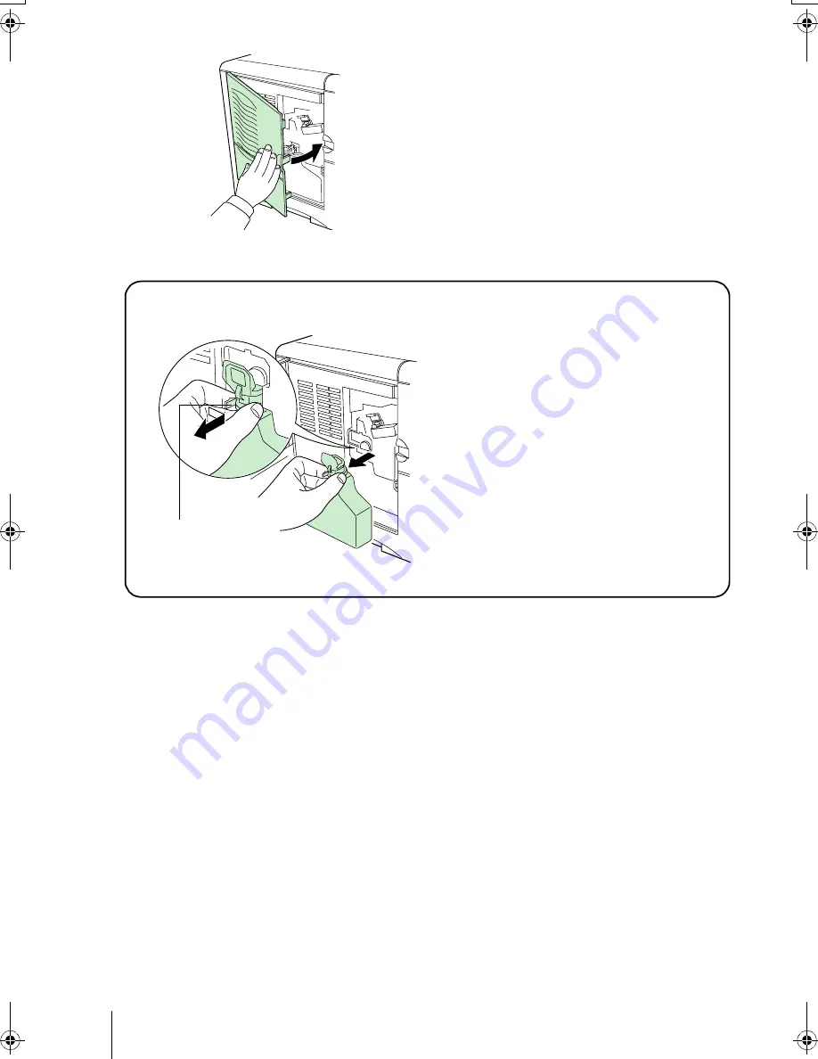
Ensuring that it is correctly inserted, 

close the left cover.

To remove the Waste Toner Box

While holding the waste toner box, 

press the lock lever and then gently 

remove the waste toner box.

Lock Lever

IFS19EE.book  Page 6  Thursday, October 18, 2001  9:51 AM

Summary of Contents for Ecosys FS-1900

Page 1: ...Installation Guide...

Page 2: ...defects in the printer s firmware contents of its read only memory This manual any copyrightable subject matter sold or provided with or in connection with the sale of the page printer are protected b...

Page 3: ...st of shipped components below List of Shipped Components STEP 1 Printer E D A B F C for U S A only Printer Power Cord F Installation Guide this booklet and other printed matter B Kyocera Mita Digital...

Page 4: ...tside Avoid locations near building entrances Sudden temperature or humidity changes Sources of high temperature for example near stoves or radiators Excessive dust Vibration Unstable surfaces and sur...

Page 5: ...computer 1 Open the printer top cover all the way 2 Take the toner container from the bag 3 With the label side down thoroughly shake the toner container in the direc tion of the arrow ten times or mo...

Page 6: ...at the positions marked PUSH HERE Whenthetonercontainerfitsintoplace it will lock with a clicking sound 7 Close the top cover To remove the toner container Pull the lock lever green colored to the rig...

Page 7: ...e wastetonerbox mustbe installed in the printer 1 Open the cap of the waste toner box 2 Open the left cover on the left side of the printer 3 Insert the waste toner box as shown in the figure The box...

Page 8: ...4 Ensuring that it is correctly inserted close the left cover To remove the Waste Toner Box While holding the waste toner box press the lock lever and then gently remove the waste toner box Lock Leve...

Page 9: ...thisstep besuretoturnoff boththeprinterandthecom puter spowerswitchesand unplugtheprinter spowerplugfromthepower outlet Failure to do so may result in electrical shock The standard Centronics parallel...

Page 10: ...the clips on both sides to fix the connector in place Plug the other end of the printer cable into the computer s parallel interface connector USB Universal Serial Bus Interface Connection 1 Plug one...

Page 11: ...should be 5 meters 16 feet or less Power Requirements To Connect the Power Cord Be sure the printer s power switch is turned off Only use the power cord supplied with the printer 1 Plug the power cord...

Page 12: ...sizes into the cas sette the size must be input into the printer on the operator panel Refer to the Operation Guide PDF file provided on the Kyocera Mita Digital Library CD ROM Standard size paper set...

Page 13: ...in the paper size window When the paper size dial is set to CUSTOM thepapersizemust be set into the printer on the operator panel See the Opera tion Guide PDF file provided on the Kyocera Mita Digital...

Page 14: ...ut insert the paper then adjust the paper guides and paper stop per to the size of the paper Adjust them so that theyare in light contact with the paper 6 Make sure that the edges of the paper are ali...

Page 15: ...right side of the front of the paper cassette to indicate the remaining paper supply When paper is exhausted the pointer will go down to the level of empty 9 If you have installed a paper cassette th...

Page 16: ...e MP tray Standard paper sizes are attached to the MP tray For stan dard paper sizes slide the guides to the position marked correspondingly 4 Align the paper with the paper guides and insert as far a...

Page 17: ...edge first Test a sample envelope on the printer and check that printing quality is satisfactory before purchasing To avoid trouble we recommend that envelopes be delivered face up using the option f...

Page 18: ...y when you wish paper to be stacked with the printed side facing up reverse order or when you are printing on envelopes postcards transparencies or thick paper This face up output tray is a separate o...

Page 19: ...ady to print as the developerunit needs to be filled with toner During this period the message display shows Please wait Adding toner 2 Wait until the READY indicator is also lit and the message displ...

Page 20: ...the printer print a status page indicating factory settings 1 Press the MENU key on the operator panel 2 Press the or key repeatedly until the message display shows Print Status Page 3 Press the ENTER...

Page 21: ...pulling the paper pull it gently so as not to tear it Torn pieces of paper are difficult to remove and may be easily overlooked deterring the jam recovery Jam at the Rear Cover 1 While pulling the pap...

Page 22: ...pull out the paper transfer unit 2 If paper is jammed before the registration roller remove it as shown in A If paper is jammed under the registration roller remove it as shown in B Registration Rolle...

Page 23: ...to correct the interference by one or more of the following measures Reorient or relocate the receiving antenna Increase the separation between the equipment and receiver Connect the equipment into an...

Page 24: ...openingsshould never be blocked by placing the product on a bed sofa rug or other similar surface This product should never be placed near or over a radiator or heat register This product should not b...

Page 25: ...cabinet has been damaged Canadian Department of Communications compliance statement This Class B digital apparatus complies with Canadian ICES 003 Avis de conformit aux normes du minist re des Communi...

Page 26: ...ent optional units PF 60 DU 60 SO 60 Trade Name Kyocera Responsible Party Kyocera Mita America Inc Address 225 Sand Road PO Box 40008 Fairfield New Jersey 07004 0008 U S A Telephone number 973 808 844...

Page 27: ...location remove the toner container waste toner box and developer unit The procedure for removing these is as follows 1 Remove the toner container and waste toner box from the printer Put the toner c...

Page 28: ...s power supply when not using the printer for extended periods of time For details on the sleep timer function and printer power consumption refer to the CD ROM instruction manual provided with the p...

Page 29: ...d to the front of the printer after the MP tray has been removed 5 Duplexer DU 60 Performs duplex printing for short edge and long edge binding Attaches to the bot tom of the printer 6 Paper Feeder PF...

Page 30: ...er programs IBM retains title to the Programs IBM owns or has licensed from the owner copyrights in the Programs 1 License Under this license you may use the Programs only with the device on which the...

Page 31: ...rtant note on the interface connectors Be sure to turn off printer power before connecting or disconnecting an interface cable to the printer For pro tection against static discharge which may be appl...

Page 32: ...ator shows which of the printer s interfaces is currently active The default is no selection Paper size indicator Indicates the paper size of the current paper cassette The default is A4 A4 size Paper...

Reviews: