background image

Contents

1 Product Overview

…………………………………………………………………

1

2 Structure and Interface

……………………………………………………………

3

2.1 Front Panel

……………………………………………………………………

3

2.2 Top Panel

……………………………………………………………………

4

3 Mounting

……………………………………………………………………………

4

3.1 Dimension Drawing

…………………………………………………………

4

3.2 Mounting Modes and Steps

…………………………………………………

5

3.2.1 DIN-Rail Mounting

………………………………………………………

5

3.2.2 DIN-Rail Dismounting

…………………………………………………

6

4 Connection

…………………………………………………………………………

6

4.1 10/100Base-T(X) Ethernet Port

……………………………………………

6

4.2 100Base-FX Ethernet Port

…………………………………………………

8

4.3 100Base-X SFP Slot

………………………………………………………

8

4.4 Grounding

………………………………………………………………

10

4.5 Power Terminal Block

……………… … ………………………………

10

4.6 DIP Switches

………………………………………………………………

12

5 LEDs

………………………………………………………………………………

13

6 Basic Features and Specifications

……………………………………………

14

7 Certificates Used for Compliance

……………………………………………

15

8 Appendix

…………………………………………………………………………

15

Summary of Contents for Opal5 series

Page 1: ...Opal5 Opal8 Series Entry Level Industrial Ethernet Switch Hardware Installation Manual Publication Date 2016 06 29 Version V1 3 No 112023031...

Page 2: ...compliance with the Directive 2011 65 EU Restriction of the Use of Certain Hazardous Substances in Electrical and Electronic Equipment RoHS including all amendments to the EU directive e g The Restric...

Page 3: ...Wear antistatic gloves or take other protective measures when operating the device Avoid any exposed metal wires because they may be oxidized or electrified Install the device in accordance with relat...

Page 4: ...dans les emplacements non dangereux seulement WARNING EXPLOSION HAZARD AVERTISSEMENT RISQUE D EXPLOSION Water gets into the equipment Equipment damage or shell damage Equipment operation or performan...

Page 5: ...odes and Steps 5 3 2 1 DIN Rail Mounting 5 3 2 2 DIN Rail Dismounting 6 4 Connection 6 4 1 10 100Base T X Ethernet Port 6 4 2 100Base FX Ethernet Port 8 4 3 100Base X SFP Slot 8 4 4 Grounding 10 4 5 P...

Page 6: ...rature range models Broadcast storm protectioncan be configured through DIP switch The series switches support DIN rail mounting Opal5 provides four 10 100Base T X Ethernet ports one 100M copper or fi...

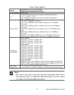
Page 7: ...s Note We reserve the right to amend the product information listed in this table without notice To obtain the latest information you can contact our sales or technical support personnel Kyland Opal5...

Page 8: ...re switch performance Caution Figure 1 Front Panel 1 Power 1 LED 2 Power 2 LED 3 10 100Base T X Ethernet port 4 10 100Base T X Ethernet port connection status LED green 5 10 100Base T X Ethernet port...

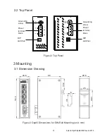
Page 9: ...Drawing Figure 3 Opal5 Dimensions for DIN Rail Mounting unit mm 3 Mounting Kyland Opal5 Opal8 IM EN June 2016 Grounding screw DIP switches Power terminal block Grounding screw Power terminal block DI...

Page 10: ...yland Opal5 Opal8 IM EN June 2016 As part of the heat dissipation system the switch housing becomes hot during operation Please use caution when coming in contact and avoid covering the switch housing...

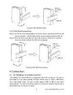
Page 11: ...vice is removed from the DIN rail completely 3 2 2 DIN Rail Dismounting 10 100Base T X Ethernet port is equipped with RJ45 connector The port is self adaptive It can automatically configure itself to...

Page 12: ...RJ45 Port RJ45 Straight through Cable Crossover Cable RJ45 RJ45 RJ45 Kyland Opal5 Opal8 IM EN June 2016 The color of the cable for RJ45 connector meets the 568B standard 1 orange and white 2 orange 3...

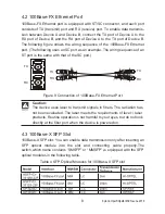
Page 13: ...ort and RX receive port To enable data transmis sion between Device A and Device B connect the TX port of Device A to the RX port of Device B and the RX port of Device A to the TX port of Device B The...

Page 14: ...shows the cable connection of the SFP optical module Insert the SFP optical module into the SFP slot in the switch and then plug the optical fiber into the TX port and RX port of the SFP module Figure...

Page 15: ...hort fiber is used the module will be burned Caution 4 4 Grounding Grounding protects the device from lightning and interference Therefore you must ground the device properly You need to ground the de...

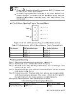
Page 16: ...n external power supply system with the allowed power range If the power LED on the front panel of the switch turns on the power supply is connected properly Wiring and mounting should meet following...

Page 17: ...the device may be damaged To comply with UL restrictions this equipment must be powered from a source compliant with SELV Caution Do not touch any exposed conducting wire terminal or component with a...

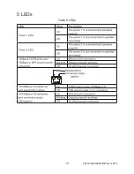
Page 18: ...13 5 LEDs Kyland Opal5 Opal8 IM EN June 2016 Table 8 LEDs...

Page 19: ...14 6 Basic Features and Specifications Kyland Opal5 Opal8 IM EN June 2016...

Page 20: ...erature 75 for Opal5 8 series and 60 for Opal5 8 E series Opal5 E 1SFP4T Opal8 E 1SFP7T Opal8 E 2SFP6T Opal5 1SFP4T Opal8 1SFP7T Opal8 2SFP6T 1 ATEX Certificate No DEMKO 17 ATEX 1822X 2 IECEx Certific...

Page 21: ...of not more than pollution degree 2 as defined in EN IEC 60664 1 The equipment shall be installed in an enclosure that provides a degree of protection not less than IP 54 in accordance with EN IEC 600...

Page 22: ...Kyland Technology Co Ltd FAX 86 10 88796678 Website http www kyland com Email support kyland com Factory Address NO 901 FLOOR8 12 BUILDING NO 2 SHIXING AVENUE30 SHIJINGSHAN DIST BEIJING 100144 CHINA...

Reviews: