background image


Chapter 3  -  Startup 


232 - V 3.11.4 

5

3.2 Operation 

Key 1 

(LEFT) 

=  DOWN 

Key 2 

(CENTER)  =  UP 

Key 3 

(RIGHT) 

=  MODE 


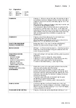
POWER ON 

Press key 1. When you press the button, the instrument name 
and software button are displayed briefly, and then the battery 
voltage is shown for 5 seconds. (full battery approx. 6.4 V, low 
battery < 5.9 V  

While the battery voltage is displayed, press key 3 and the unit 
is powered on (length display mode) . 

You can select a cable when the instrument is switched off by 
pressing key 1 and then key 2. Use keys 1 or 2 to select the 
cable type and then press key 3. Press key 3 to switch from the 
length display to the return loss measurement (the shortening 
factor and cable loss/100 m at 50 MHz are preset for the 
measurement.


POWER OFF 

Press key 2 and 3 simultaneously, the unit shuts down. 

Automatically after 4 min of not actuated. 

When the battery voltage drops to 5.9 V, this is shown in the 
display. At 5.5 V, the instrument shuts down.


SELECT MEASUREMENT 
RANGE / PARAMETERS 

Briefly press key 3. The cursor is activated (highlighted). 

Selected the measurement range with key 1 and 2. 

MOVE CURSOR 

With key 1 or 2. Fast cursor movement  

  Hold the key down. 

Switchover of the measurement range is automatic when the 
cursor crosses a band limit. 

SELECTING VARIOUS 
SETTINGS: 


LENGTH RANGE 

 RESOLUTION 
  OUTPUT PULSE WIDTH 
 DIGITAL FILTER 
 MEMORY LOCATION 
 SHORTENING FACTOR 


Press and hold key 3 (0.5 seconds) until the symbol required is 
highlighted. 

Press keys 1 and 2 to change the value selected. 

Press keys 1 and 3 simultaneously to permanently save the 
width of the output pulse and the shortening factor. 

To return to the default setting 

, press key 3 briefly.


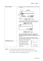
RETURN LOSS 

(REFLECTION LOSS dbRL) 

DETERMINING 

Position the cursor on the echo pulse peak and read out the 
return loss at the bottom left of the display. 

The cable loss/100 m at 50 MHz is shown in the cable 
selection at the bottom right of the display and must be set in 
accordance with the cable data sheet (see attachment). If the 
cable loss is set correctly, the instrument displays the actual 
(local) return damping. 

The cable's pulse attenuation is deducted and the pulse 
amplification is adjusted automatically. 

A pulse width of 20 ns (medium pulse) is best suited for 
measurement.


DIGITAL FILTER 

In order to suppress or minimise interference in the curve 
displayed due to external voltages on the cable, a digital mean 
filter “Fi” can be activated using keys 1 or 2. The curve display 
is then extended to 3 seconds. 

PULSE AMPLIFIER SETTING  

Press key 3 briefly and set the amplification with keys 1 or 2.  

Summary of Contents for IRM 232

Page 1: ...hapter 1 Notes on use and safety 2 1 1 Notes on use 2 1 2 Safety 2 Chapter 2 Technical data 3 Chapter 3 Startup 4 3 1 Technical description 4 3 1 1 Basics of pulse reflectometry 4 3 1 2 Measuring principle 4 3 2 Operation 5 Appendix Cable types 8 ...

Page 2: ... danger the user must observe the instructions and warnings contained in this operator manual Before adjustment maintenance repair or replacement of parts requiring the instrument to be opened you must disconnect it from all voltage sources Should adjustment maintenance or repair of the opened instrument subsequently require application of voltage this may only be performed by a specialist who is ...

Page 3: ...s Dynamic range 44dB vertically in amplitude Sensitivity 70dB Digital filter Can be activated to suppress interference of external voltage on the cable Impedance 75Ohm Measurement connector IEC socket 75Ohm Measurement pulse output 4 Volt needle pulse of 5ns 20ns or 100ns pulse width POWER SUPPLY Power supply NIMH 6V 700mAh or power supply 12 to 24 Vdc or Vac Current drain 80mA Operation max 8 h C...

Page 4: ...dar system in which the transmitted signal represents a very fast jump function and the reflecting signal can be observed on its display The faster the rise of the measurement pulse the better is the resolution time equals distance The amplitude is in direct relation to the impedance meaning that measurement of matching is possible The pulse reflectometer method is thus suitable for measuring all ...

Page 5: ...ement range is automatic when the cursor crosses a band limit SELECTING VARIOUS SETTINGS LENGTH RANGE RESOLUTION OUTPUT PULSE WIDTH DIGITAL FILTER MEMORY LOCATION SHORTENING FACTOR Press and hold key 3 0 5 seconds until the symbol required is highlighted Press keys 1 and 2 to change the value selected Press keys 1 and 3 simultaneously to permanently save the width of the output pulse and the short...

Page 6: ...sor is placed at the impulse start Storage of this with pressing key 1 and 3 at the same time Back to initial state with key 3 SAVING THE SETTINGS Press keys 1 and 3 simultaneously to save the settings preselected in the display They are then available when the instrument is switched on LOW BATTERY WARNING AND SHUTDOWN If the battery voltage drops to 5 9 V the voltage is shown flashing at the top ...

Page 7: ...rmined from the pulse echos If a wide output pulse is used for measurement the pulse echos are more pronounced Defective branches and splitters then produce stronger pulse echos SHORTENING FACTOR Coaxial cable with PE dielektric 0 66 Coaxial cable with foam PE 0 82 0 78 0 95 Stripline with foam insulation 0 83 Coaxial cable with air insulation 0 9 0 88 0 92 Electric cable 0 49 0 57 ca 0 53 Attenti...

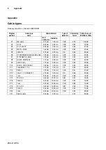
Page 8: ...7 75100 AKZ 3 5 RG6 1 00 mm 4 60 mm CPE 0 85 4 4 dB P8 LCD 95 DIGITAL 94 1 13 mm 4 80 mm CPE 0 85 4 3 dB P9 COAX 6 LG 1 70 mm 6 95 mm CPE 0 89 2 3 dB P10 LCM 14 MK 15 KOKA 7 1 63 mm 7 20 mm CPE 0 84 2 8 dB P11 TELASS B1 1 7 3 1 10 mm 7 25 mm PE 0 66 3 8 dB P12 PRG 11 1 55 mm 7 25 mm CPE 0 81 2 7 dB P13 1 ikx 1 1 7 3 KOKA 741 1 10 mm 7 30 mm PE 0 66 3 3 dB P14 1 nkx 2 20 mm 8 80 mm PEH 0 88 1 8 dB ...

Reviews: