


14
KWE P
/N 3940
46 Ve
rsatronik
502 a
nd 502D
MODBUS G
atewa
y V1
.0 F
eb
2
014 Te
chni
ca
l i
nformation subj
ec
t to
ch
ange
w
ithout noti
ce
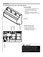
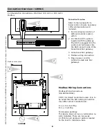
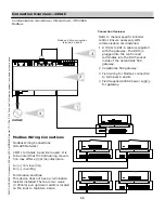
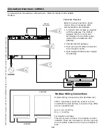
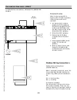
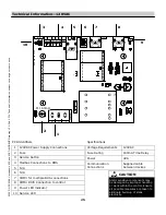
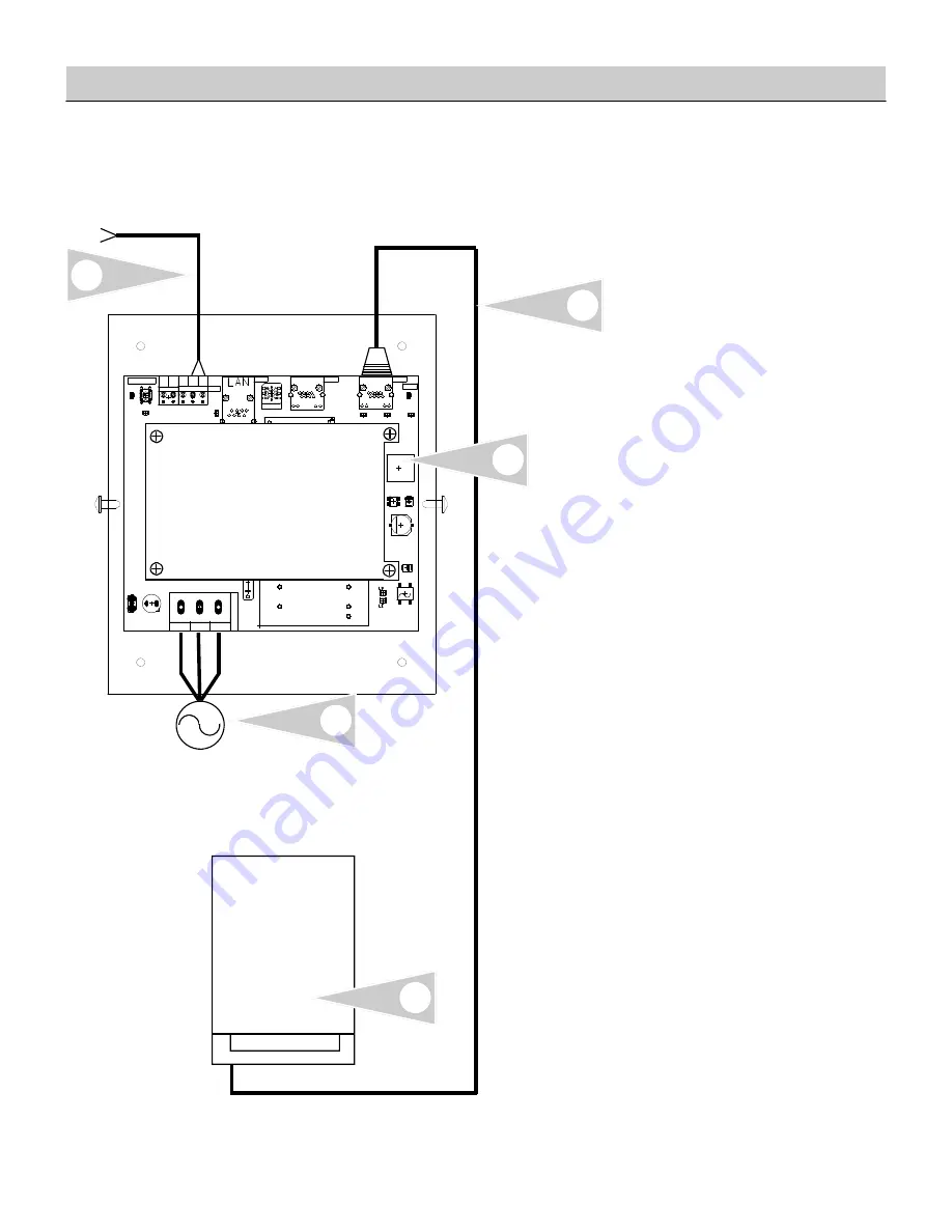
Connection Overview—120VAC
Communication connections—Vitodens 200, WB2B, HO1
Modbus
!"
#
$
%
%
&
'
(
)
(
*
(
(
&
+
&
+
Modbus
connection
120VAC
4
Refer to manual specific to
boiler control. Ensure necessary
LON communication card
installed.
1 A 3’/91cm CAT-5 cable is
supplied with the gateway.
The RJ45 is plugged into the
control and terminates into
the RJ45 socket inside of the
Versatronik 502 gateway.
2 Versatronik 502 gateway.
3 Field wiring for Modbus
connection to terminals A
and B.
4 Plug-in power cord for
120VAC Versatronik 502
gateways.
5 Refer to boiler manual with
respect to installing LON
communications card inside
of boiler control.
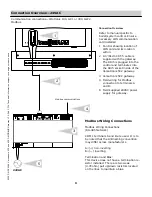
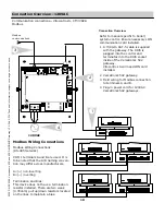
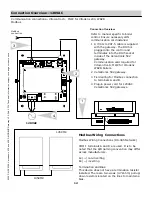
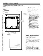
Connection Overview
2
1
3
5
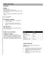
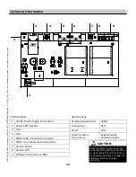
Modbus Wiring Connections
(RS-485 Network)
COM 1 terminals A and B are used. It is
to be noted that the A/B naming con-
vention may differ across manufactur-
ers.
A=(+) non-inverting
B=(—) inverting
Termination and Bias:
This device does not have a termina-
tion resistor installed. There are two
weak (4.7Kohm) pull up/down resistors
located on the lines to maintain a bias.
Modbus Wiring Connections


