background image

20    |    kvm-tec

kvm-tec    |    21

2. INSTALLATION Of The exTeNder

2.4 STArT UP

To start up the system without switch:

1.  Make sure that the two monitors and the computer are switched on.
2.  If you are using a Network Switch, connect the power supply to an earthed wall socket. 
3.  Connect both extender 

power supplies

 (C) to an earthed wall socket. Both extenders will  


start an initialisation process. The red status LED blinks a few seconds. After a few seconds  


the status LED lights green. The monitor will displays your computer’s desktop or any open  


applications.

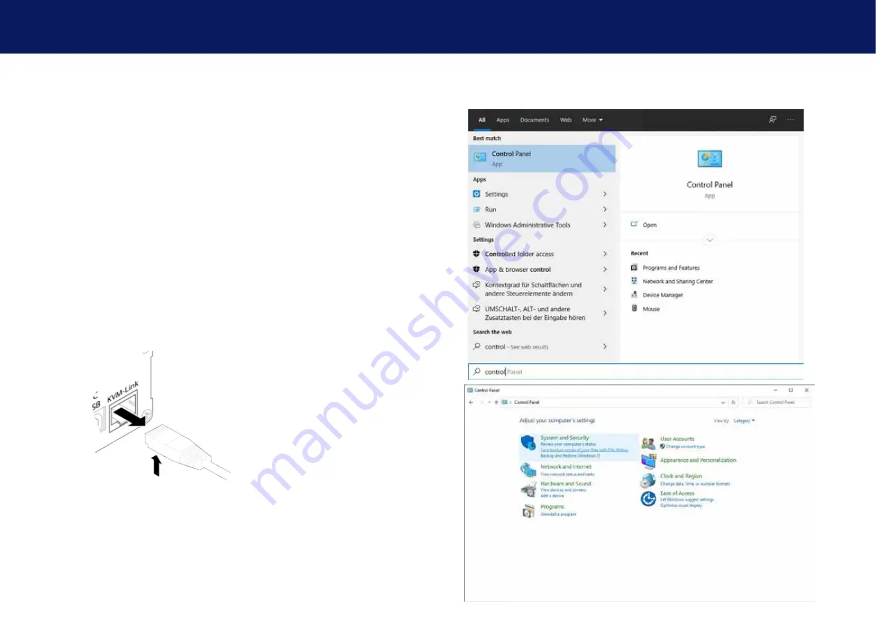
2.5 rEMoVIng A CATx CABlE

To remove a CATx cable:

•  Press the latch down and slowly pull the cable out.

2. InSTAllATIon oF ThE ExTEndEr

2.6 BEST PrACTICE For WIndoWS 10

disable USB Energy Savings in Windows 10

Summary of Contents for 6031

Page 1: ...Bflex single in Kupfer 6031L CPU LOCAL 6031R CON REMOTE 6032 SET USBflex single in Fiber 6032L CPU LOCAL 6032R CON REMOTE www kvm tec com Check out our Installation Channel connect collaborate communicate control kvm tec C 4 USB flex ...

Page 2: ...and an er gonomic and quiet workplace for all users is possible CONTROL your application in a much better way with all our in house developments like USB 2 0 transmission video compression without latency only one cable for USB and video transmission zero latency With our unique features each user can access multiple PC sources and can control and ope rate up to 16 screens with one mouse keyboard ...

Page 3: ... described and for the areas of application as stated When passing the product to a third party be sure to also supply all instructions and other relevant documentation Following proper use and maintenance your USBflex KVM Extender will bring you joy for many years to come 1 1 Intended Use This product is intended to be used as a device to increase the distance that a keyboard monitor and mouse ca...

Page 4: ...diately and stop using the product If the product is not installed and used in accordance with this manual it may cause disruptive interference with radio or television reception or affect other electronic products in residential areas Use shielded cables only to connect the components in order to avoid such interference Non compliance invalidates the permission to operate this product Only the ma...

Page 5: ...25ºC to 80 13 to 176 F Relative Luftfeuchtigkeit max 80 non condensing Humidity for storage max 80 non condensing Housing material anodized aluminum Dimension 109 x 43 x 107 5 mm 4 29 x 1 69 x 4 23 inch Weight 295 g 0 65 lb Local CPU 295g 0 65 lb Remote CON Shipment weight 1005g 2 21 lb per set single MTBF 82 820 calculated hours 10 years 1 4 About the product USBflex Single copper Remote CON Exte...

Page 6: ...1A LED STATUS yellow LINK ok green Video ok green blinking Video and USB activityx 1 2 3 1 5 Product elements USBflex single fiber Remote CON Extender Nr Name Function 1 USB USB from Videocamera Photocamera Joystick 2 kvm link Connection for CAT5 6 7 cable 3 dc Connection power supply 12V1A LED STATUS yellow LINK ok green Video ok green blinking Video and USB activityx 4 2 1 3 ...

Page 7: ...o PC 2 kvm link Connection for CAT5 6 7 cable 3 dc Conenction 12V1A power supply LED STATUS yellow LINK ok green Video ok green blinking Video and USB activity 1 2 3 1 6 Product elements USBflex Backside Nr Name Function 1 LED Status Display the status of the extender 2 Reset Button for reset 4 1 2 1 ...

Page 8: ...should be checked for damage In case of damage due to transport inform the carrier immediately Before delivery the product is checked for its function and its operating safety Make sure that the packaging contains the following content USBflex Single copper Local CPU Unit 1 x UB1 local CPU 1 x wall power supply unit 12 V 1A EU plug or Int plug 1 x USB cable 1 8m 5 9ft 4 x rubber feet Remote CON Un...

Page 9: ... and a power supply For 4 Single Extender in one Rack Under table mounting kit Part Nr 6231 UMK FLEX The Under Desk Mounting kit is for underdesk mounting of the USBflex extender Din Rail mounting Part Nr 6235 DINMK FLEX The DIN rail mounting is used for space saving installation in control cabinets or on DIN rails The attachment to the USBflex Extenders is possible in several ways Vesa mounting P...

Page 10: ... use for many years MTBF approx 10 years Network cable CAT5e 6 7 up to 150m 492ft USB from Photo camera USB from Joystick USB from Video camera 2 3 Quickinstallation USBflex single fiber Power plug 12V 1A Power plug 12V 1A USB to PC Quick Installation USBflex Fiber local CPU remote CON 1 Connect the CON Remote and the CPU Local Unit to the included 12V 1A power supply 2 Now connect the USB cable t...

Page 11: ...h extender power supplies C to an earthed wall socket Both extenders will start an initialisation process The red status LED blinks a few seconds After a few seconds the status LED lights green The monitor will displays your computer s desktop or any open applications 2 5 Removing a CATx cable To remove a CATx cable Press the latch down and slowly pull the cable out 2 INSTALLATION of the extender ...

Page 12: ...22 kvm tec kvm tec 23 2 INSTALLATION of the extender 2 INSTALLATION of the extender ...

Page 13: ...about installation Manual download www kvm tec com or kvm tec Installationchannel on our homepage personally 43 2253 81912 kvm tec Support support kvm tec com Phone 43 2253 81912 30 4 First Aid USB is not working No Power No LED Check the powerplug Is the power supply ok Try another Unit Try reprogramming the Unit by using a JTAG programmer Contact kvm tec support Are the USB Devices plugged in co...

Page 14: ...ould otherwise be caused by improper treatment of waste equipment The recycling of materials contributes to the conservation of natural resources Therefore do not dispose of your old electrical and electronic equipment with the unsorted municipal waste The packaging is made of environmentally friendly materials which may be disposed through your local recycling facilities By disposing of the packa...

Page 15: ... standards Class D ISO IEC 11801 2002 or EN 50173 1 2002 Schema EIA TIA 568 B Only use shielded installation cable with min cross section of 24 AWG throughout the length The shield should be contiguous and connected to both ends A shielded patch cable is allowed for connection to the device Schema EIA TIA 568 B 8 Requirements network switch The entire switching network system requires its own dedi...

Page 16: ...43 0 2253 81 912 Fax 0043 0 2253 81 912 99 Email support kvm tec com Web www kvm tec com Find our newest updates and FAQs on our homepage http www kvm tec com 9 adDress Phone email kvm tec Inc USA Sales p 1 213 631 3663 43 225381912 22 email officeusa kvm tec com kvm tec ASIA PACIFIC Sales p 9173573 20204 email sales apac kvm tec com kvm tec China Sales P 86 1360 122 8145 email chinasales kvm tec ...

Reviews: