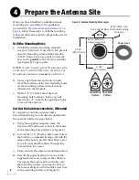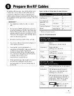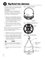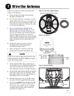
18
Linear Wiring
Follow these steps to connect linear receivers to
the TracVision system.
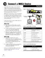
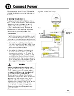
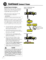
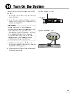
NOTE:
The linear universal quad LNB is required.
Connecting 1-4 Linear Receivers
a.
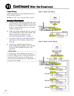
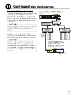
Connect an RF cable from the “Receiver” jack
on the TV-Hub to the “Satellite In” jack on the
first receiver (see Figure 27).
This receiver will
be able to control satellite selection in Automatic
satellite switching mode.
b.
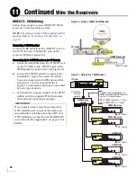
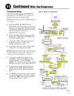
When connecting multiple receivers, connect
a grounding block in-line with each RF cable
from the antenna (see Figure 28 and
“Grounding Requirements” on page 27
c.
Connect the other end of the RF1 cable from
the antenna to the “Antenna” jack on the
TV-Hub.
d.
Connect any other RF cables from the
antenna (RF2, RF3, and RF4) to the “Satellite
In” jack on each additional receiver (see
Figure 27: Wiring 1 Linear Receiver
TV-Hub
Wi-Fi
LEN=1
10-30V
POWER
MAX CURRENT 9.5A
NMEA 0183
B
A
FUSE
ETHERNET
DSWM
RECEIVER
GROUND
ANTENNA
RESET
NMEA 2000
DC IN
Receiver
AC Power
Satellite In
Antenna
Receiver
RF1
TV-Hub
Wi-Fi
LEN=1
10-30V
POWER
MAX CURRENT 9.5A
NMEA 0183
B
A
FUSE
ETHERNET
DSWM
RECEIVER
GROUND
ANTENNA
RESET
NMEA 2000
DC IN
Antenna
Receiver
AC Power
Satellite In
Receiver
RF1
Receiver
AC Power
Satellite In
Receiver
AC Power
Satellite In
Receiver
AC Power
Satellite In
RF4
RF3
RF2
Grounding
Blocks
Figure 28: Wiring 2 to 4 Linear Receivers
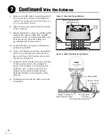
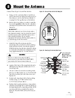
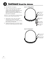
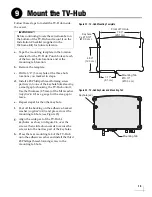
To enable any of the additional receivers to
control satellite selection, install an optional IP
AutoSwitch (KVH part no. 72-0634) in-line
with the receiver’s RF input. See Appendix B
on
for details.
IMPORTANT!
Continued
Wire the Receivers
11
Summary of Contents for TracVision TV10
Page 1: ...TracVision TV10 Installation Guide ...
Page 53: ......

