background image

3

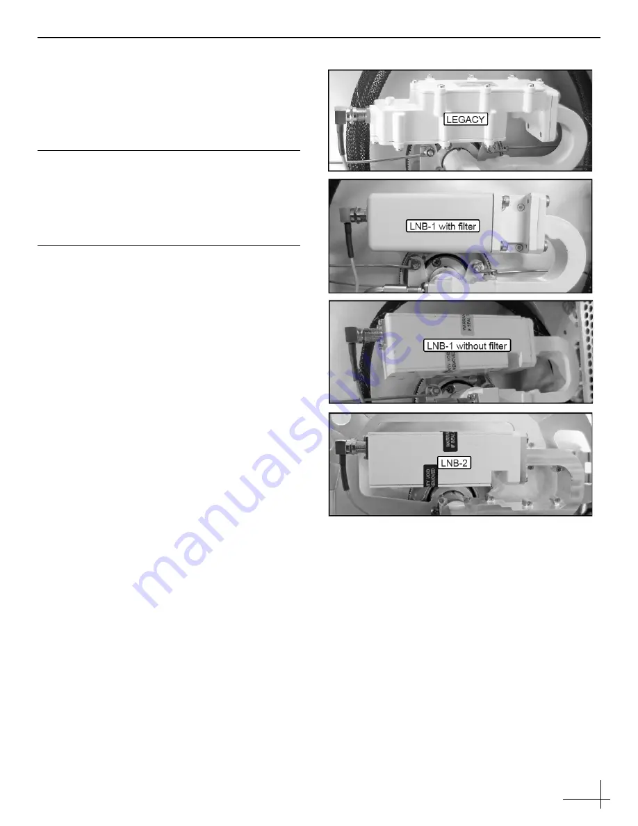
Step 2 - Identify the LNB Type

There are four possible LNB types (see Figure 3). The 
replacement instructions are identical for each with 
one exception - the Legacy LNB must be replaced 
with an LNB-1 with attached filter. Legacy LNBs are 
no longer available. 

NOTE: Type 2 LNBs are labeled as such. Older LNBs are 
not labeled.

Important!

Be sure to replace the LNB with an LNB of the same 
type, with the exception of the Legacy LNB. The 
Legacy LNB must be replaced with an LNB-1 with 
filter.

Figure 3:  LNB Types (from oldest to newest)

Summary of Contents for TracPhone V3 LNB

Page 1: ...ed technical assistance please contact KVH Technical Support Europe Middle East Africa Asia Pacific Phone 45 45 160 180 Email mvbsupport kvh com North South America Australasia Phone 1 866 701 7103 U S only or 1 401 851 3806 Email mvbsupport kvh com The following instructions explain how to replace the LNB in a TracPhone V3 V3 IP V3 HTS antenna NOTE Your antenna might have parts that differ from t...

Page 2: ...me to the baseplate see Figure 2 Carefully lift the radome straight up until clear of the antenna assembly and set it aside in a safe place If you keep the radome topside secure it with a lanyard to prevent it from falling overboard Do not place the radome on a hot steel deck the heat may warp the radome CAUTION For your own safety be sure to disconnect power from all wired components before perfo...

Page 3: ...y LNB must be replaced with an LNB 1 with attached filter Legacy LNBs are no longer available NOTE Type 2 LNBs are labeled as such Older LNBs are not labeled Important Be sure to replace the LNB with an LNB of the same type with the exception of the Legacy LNB The Legacy LNB must be replaced with an LNB 1 with filter Figure 3 LNB Types from oldest to newest ...

Page 4: ...e RF cable is aligned to prevent any interference when the feed assembly rotates Hand tighten then tighten with a 7 16 torque wrench set to 15 in lbs 5 Inspect the inside of the antenna to make sure you have not left any tools or debris inside 6 Reinstall the radome onto the antenna securing it with the three new 10 32 screws supplied in kit 7 Reconnect power to the antenna 8 Test the system for n...

Reviews: