background image

Kvaser U100S User’s Guide

11 (24)

3.7

LED Indicators

A Kvaser U100S device has two traffic LED bars where part of each LED bar is
also used as a status area. The TX LED Bar has a status area towards the USB
end of the bar, and the RX LED bar has a status area towards the CAN end of the
bar. This is shown in Figure 7.

Figure 7: The TX and RX LED bars on the Kvaser U100S include status areas.

Different colors are used for different types of information and different blink
patterns define the current state, see Table 3 and Table 4 on Page 12.

Color

Information type

Yellow

Traffic

Green

Status

Red

Error

White

Alert

Blue

System

Table 3: Different types of information.

Kvaser AB, Mölndal, Sweden — www.kvaser.com

Summary of Contents for U100S

Page 1: ...e believe that the information contained herein was accurate in all respects at the time of printing Kvaser AB cannot however assume any responsibility for errors or omissions in this text Also note that the information in this document is subject to change without notice and should not be construed as a commitment by Kvaser AB ...

Page 2: ...Kvaser U100S User s Guide 2 24 This page is intentionally left blank Kvaser AB Mölndal Sweden www kvaser com ...

Page 3: ...y 10 3 7 LED Indicators 11 3 8 Interface mode 12 3 9 The t programming language 13 3 10 Restrictions in t functionality 14 3 11 Updating the firmware 16 3 12 Technical data 17 4 Troubleshooting 18 5 Safety Instructions 19 5 1 Intended Use 19 5 2 Usage Warning 19 6 Disposal and Recycling Information 20 7 Legal Acknowledgements 21 7 1 EU Regulatory Compliance 21 7 2 FCC Regulatory Compliance 22 7 3 ...

Page 4: ...About this manual This manual is intended for Kvaser U100S users This document contains a description of the hardware s properties and general instructions for connecting the device to a computer Kvaser AB Mölndal Sweden www kvaser com ...

Page 5: ...ith a high timestamp precision and is compatible with applications that use Kvaser s CANlib This guide applies to Kvaser U100S devices using at least firmware and driver versions listed in Table 1 For minimum compatible firmware and driver versions of Kvaser U100S see Table 7 on Page 16 Device Product Number Firmware Driver Windows Linux Kvaser U100S 73 30130 01181 6 v3 24 v5 36 kcany mhydra Table...

Page 6: ...e of glass fibre reinforced polyamide overmolded with TPE Intuitive LED UI Reinforced galvanic isolation design validated with 5000 VAC rms applied for 60 s Industrial grade temperature range 40 C to 85 C 20 000 msg s each timestamped with a resolution of 1 µs Kvaser MagiSync automatic time synchronization see Section 3 3 Kvaser MagiSync on Page 8 for more details Fully compatible with application...

Page 7: ...w to update the firmware see Section 3 11 Updating the firmware on Page 16 The latest version of the driver and firmware can be downloaded from www kvaser com download The firmware is downloaded and installed directly on the Kvaser U100S and the driver is installed on the host computer After the driver has been installed on the host computer the firmware may then be downloaded and installed on the...

Page 8: ...MagiSync Time synchronization is needed to achieve accurate and precise time stamping between several PC to bus interfaces connected to one PC Since each PC to bus interface uses its on board clock to set the time stamps Kvaser MagiSync is an innovative way to synchronize several different Kvaser USB interfaces You do not need external cables you get instant synchronisation when you connect the Ma...

Page 9: ... MagiSync Group then you are ready to go When connected correctly all units are synchronized achieving a high precision virtual clock accurate to the microsecond 3 4 CAN connection The Kvaser U100S has one CAN channel The CAN connector for the Kvaser U100S is the 9 pin D SUB connector see Figure 5 which has the pinout described in Table 2 on Page 10 Figure 5 The 9 pin D SUB CAN connector Kvaser AB...

Page 10: ... not contain any CAN bus termination because their inclusion could cause severe disturbance in a system which is already correctly terminated For laboratory or testing use the exact value of the termination resistors is not always critical Sometimes a single terminator is sufficient For production proper termination is essential If you see error frames on the bus you should check the termination T...

Page 11: ...s area towards the CAN end of the bar This is shown in Figure 7 Figure 7 The TX and RX LED bars on the Kvaser U100S include status areas Different colors are used for different types of information and different blink patterns define the current state see Table 3 and Table 4 on Page 12 Color Information type Yellow Traffic Green Status Red Error White Alert Blue System Table 3 Different types of i...

Page 12: ...r Power is on On White Waiting for USB configuration Fast Blink Blue CAN channel is bus on On Green CAN channel traffic On Yellow Dynamic Yellow Error frame Dynamic Red CAN channel is error passive Fast Blink Red CAN overrun On Red Firmware update Slow Blink Blue Locate hardware Slow Blink White Slow Blink White Table 5 LED inidications in interface mode The Kvaser U100S has one TX LED Bar and one...

Page 13: ...rresponding to 50 bus load in each direction for a total of 100 bus load The image on the right shows the unit transmitting data corresponding to 100 bus load Figure 9 The total size of the LED Bars is proportional to the bus load Both images indicate a bus load of 100 3 9 The t programming language The Kvaser t programming language is event oriented and modelled after C It can be used to customiz...

Page 14: ...N bus events for example to speed up file transfer protocols or to simulate missing hardware For more information see the Kvaser t Programming Language guide that can be downloaded at www kvaser com download 3 10 Restrictions in t functionality The Kvaser U100S is a dedicated CAN interface and as such does not contain real time clock RTC logger or SD card functionality neither does the Kvaser U100...

Page 15: ...og kvIoPinGetOutputAnalog Predefined File I O Functions fileOpen fileClose fileGets fileReadBlock filePuts fileWriteBlock fileSeek fileDelete Predefined XML Functions xmlOpen xmlClose xmlGet Predefined t Program Related Functions scriptLoad Predefined Logger Related Functions filterDropMessage loggerStatus loggerStart loggerStop Other Predefined Functions timeGetDate Table 6 Functionality in the t...

Page 16: ...wing the Firmware Update Instructions read and follow those carefully To check the current firmware version open Kvaser Device Guide which can be found in the Control Panel Select Kvaser U100S in the tree view to the left and click on the channel The firmware revision information now appears in the right half of the window The absolute minimum firmware and driver versions needed in order to use Kv...

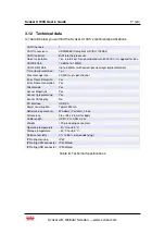
Page 17: ... Max message rate 20 000 msg s per channel Error Frame Detection Yes Error Frame Generation Yes Silent mode Yes Kvaser MagiSync Yes Kvaser t programming Yes Kvaser CANtegrity No PC interface USB 2 0 Power consumption Typical 250 mA Software requirements Windows 7 or later Linux Dimensions 38 x 128 x 26 mm for body Cable length USB 1 0 m CAN 0 3 m Weight 170 g including connectors Operating tempera...

Page 18: ...nel to verify that the computer can communicate with the Kvaser U100S If the firmware version shown is all zeros there are communication problems If the LED Bar or the status indication is not flashing or does not light up at all check the power supply Kvaser AB Mölndal Sweden www kvaser com ...

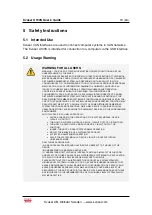
Page 19: ...IONS AND OPERATIONS WHICH MAY RESULT IN SERIOUS PHYSICAL HARM OR DEATH OR CAUSE DAMAGE TO EQUIPMENT DEVICES OR THE SURROUNDING ENVIRONMENT WITH THIS DEVICE YOU MAY POTENTIALLY CAUSE A CHANGE IN THE OPERATION OF THE SYSTEM MODULE DEVICE CIRCUIT OR OUTPUT TURN ON OR ACTIVATE A MODULE DEVICE CIRCUIT OUTPUT OR FUNCTION TURN OFF OR DEACTIVATE A MODULE DEVICE CIRCUIT OUTPUT OR FUNCTION INHIBIT TURN OFF ...

Page 20: ... When this product reaches its end of life please dispose of it according to your local environmental laws and guidelines For information about Kvaser s recycling programs visit https www kvaser com en kvaser recycling policy html Kvaser AB Mölndal Sweden www kvaser com ...

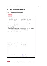
Page 21: ...atus allowing traceability Product Kvaser U100S Type 73 30130 01181 6 The object of the declaration described above is in conformity with the relevant Union harmonisation legislation Electromagnetic Compatibility EMC Directive 2014 30 EU Art 6 RoHS recast Directive 2011 65 EU Art 4 1 The following harmonised standards and technical specifications have been applied title date of standard specificat...

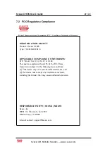
Page 22: ... 15 107 15 109 This device complies with part 15 of the FCC Rules Operation is subject to the following two conditions 1 This device may not cause harmful interference and 2 this device must accept any interference received including interference that may cause undesired operation RESPONSIBLE PARTY IN USA NAME Kvaser Inc 23881 Via Fabricante Suite 503 Mission Viejo CA 92691 Internet contact suppor...

Page 23: ... logo and Reader are either registered trademarks or trademarks of Adobe Systems Incorporated in the United States and or other countries MagiSync is a trademark of Kvaser AB DeviceNet is a trademark of Open DeviceNet Vendor Association Inc NMEA 2000 is the registered trademark of the National Marine Electronics Association Inc For information about Kvaser related CAN patents see www kvaser com pa...

Page 24: ...Kvaser U100S User s Guide 24 24 8 Document Revision History Version history for document UG_98225_U100S Revision Date Changes 1 0 2021 09 07 Initial version Kvaser AB Mölndal Sweden www kvaser com ...

Reviews: