


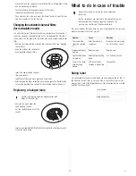


Preparing for installation
As the inner frame and chimney were joined together for transport, you
must first of all separate these parts. Moreover, the mesh with the fat filter
must be removed from under the fume trap.
–
Pull both chimney panels up out of the inner frame.
–
Undo both knurled screws holding
the metal mesh under the fume
trap.
–
Remove the mesh and the fat fil-
ter.
Drilling the attachment holes
In the box you will find a cardboard drilling template for marking the holes.
–
First determine the centre of the cooking zone and transfer this point to
the ceiling or carrier plate.
–
Hold the drilling template against the ceiling so that the marked point and
the centre of the template lie over each other.
The centre of the tem-
plate serves to position it. Only the four outer holes have to be dril-
led.
–
Turn the template so that the ima-
ginary line between any two dril-
ling points is parallel to the coo-
ker front.
Important:
If you drill the holes
elsewhere, you cannot install the
hood so that the control part is
facing in the same direction as
the control elements of the coo-
king zone.
When marking the holes, bear in mind that the power cable and, where app-
licable, the control line of the external motor, are passed through the ex-
haust opening into the hood. If the cables are laid accordingly, you can ea-
sily install them in the chimney.
–
Fastening to the ceiling:
Drill the four holes you have marked with a
10 mm bit and insert the dowels.
–
Fastening to a carrier plate:
Drill the holes you have marked with an
8 mm bit.
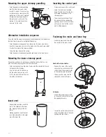
Attaching recirculating venting (recircula-
ting operation only)
–
Fit the reduction piece (B) firmly
to the vent (D) by the motor.
–
Place the deflector (A) with the ex-
haust outlet facing outwards on
the reduction piece (B).
Mounting the inner frame
You should now call in someone to help you.
–
Before you start hanging up the hood, please provide enough free space
under the installation point by, for example, moving the cooker away pro-
visionally.
–
Then try out whether the top chimney panel can be pushed from below
over the lower inner frame (with motor). If so, proceed with the following
steps, if not, please first read the section “Alternative installation sequen-
ce” on page 21.
Warning! When the hood is installed, the distance
between the lower edge of the hood and the cooker must
be at least 650 mm.
–
Screw the the upper inner frame
to the ceiling with the braces to
the side and the motor exhaust
outlet to the rear.
Fastening to a carrier plate:
Four screws M6 x 80 with was-
hers and nuts.
–
Insert the lower inner frame far
enough until the lower edge is at
least 700 mm above the cooking
zone.
–
Clamp the inner frame tight into
the top struts. The appropriate
hexagon socket screw key is provi-
ded. Make sure that the screws
are tightened well.
Mounting the exhaust pipe (venting operation
only)
If you want to operate the appliance in extraction mode, you must insert an
exhaust pipe before you mount the chimney panelling.
–
Insert the enclosed exhaust pipe a
little way into the exhaust opening
in the ceiling and then push it
onto the bottom opening in the fra-
me.
–
Fasten the pipe at the top and bot-
tom with the enclosed clips.
line parallel to the cooker front
front
rear
20
IKD 954.1