background image

39 

The control panel displays [ E ]: 

  The electronic system is defective. 

  Disconnect and replug the hob. 

  Call after sales 

One or all cooking zone cut-off: 

  The safety system functioned. 

  You forgot to cut-off the cooking zone for a long time. 

  One or more sensitive keys are covered. 

  The pan is empty and its bottom overheated. 

  The hob also has an automatic reduction of Booster level and breaking Automatic 

overheating 

Continuous ventilation after cutting off the hob: 

  This is not a failure, the fan continuous to protect the electronic device. 

  The fan cooling stops automatically. 

The automatic cooking system doesn’t start-up: 

  The cooking zone is still hot [ H ]. 

  The highest Booster level is set [ 9 ]. 

The control panel displays [ U ]: 

  Refer to the chapter “Keep warm“. 

The control panel displays [ II ]: 

  Refer to the chapter “Stop&Go“ 

The control panel displays [   ] or [ Er03 ] : 

  An object or liquid covers the control keys. The symbol disappear as soon as the key is 

released or cleaned. 

The control panel displays [ E2 ] : 

  The hob is overheated, let it cool and then turn it on again. 

The control panel displays [ E8 ] : 

  The air inlet of the ventilator is obstructed, release it. 

The control panel displays [ U400 ] : 

  The hob is not connected to the network. Check the connection and reconnect the hob. 

The control panel displays [ Er47 ] : 

  The hob is not connected to the network. Check the connection and reconnect the hob. 


If one of the symbols above persists, call the SAV. 


Summary of Contents for KI9560.0SR

Page 1: ...KI9560 0SR ...

Page 2: ... SENSORSCHALTFELDER 9 SLIDER AUSWAHLZONE UND ZEITSCHALTUHR AUSWÄHLUNG 9 KOCHFELD EIN UND AUSSCHALTEN 10 TOPFERKENNUNG 10 RESTWÄRMEANZEIGE 10 BOOSTER UND DOPPEL BOOSTER FUNKTION POWERSTUFE 11 ZEITSCHALTUHR 12 ANKOCHAUTOMATIK 13 STOP GO FUNKTION 13 MEMORY FUNKTION 14 WARMHALTEFUNKTIONEN 14 AUTOMATISCHE BRÜCKE UND BRÜCKEN FUNKTION 14 KINDERSICHERUNG VERRIEGELUNG DER KOCHMULDE 15 CHEFKOCH FUNKTION 15 ...

Page 3: ...det werden und ist nicht für gewerbliche Zwecke bestimmt Alle Etiketten und Aufkleber des Glases wegnehmen Das Gerät darf nicht abgeändert werden Verwenden Sie das Kochfeld nicht als Arbeits oder Abstellfläche Die Sicherheit ist nur gewährleistet wenn das Gerät mit einem Schutzleiter verbunden ist der den gültigen Vorschriften entspricht Der Anschluss des Gerätes an das Elektronetz darf nicht über...

Page 4: ...tigt werden Metallische Gegenstände wie Messer Gabel Löffel und Topfdeckel sollten nicht auf dem Kochfeld abgelegt werden da sie heiß werden könnten Allgemein legen Sie keine metallischen Gegenstände z B Löffel Topfdeckel usw auf die Induktionsfläche da sich diese bei Betrieb unter Umständen erwärmen können Bedecken Sie nie die Kochfläche mit einem Lappen oder einer Schutzfolie diese könnten sehr ...

Page 5: ...Sie trotzdem auf die heißen Kochzonen gelangen schalten Sie das Gerät bitte aus und entfernen Sie diese Stoffe noch im heißen Zustand Da die Kochzonen heiß sind besteht Verbrennungsgefahr Legen Sie keine Gegenstände auf dem Kochfeld ab Stellen Sie in keinem Fall heißes Kochgeschirr auf der Steuerung ab Die Elektronik unter dem Glas könnte beschädigt werden Befindet sich unter dem eingebauten Gerät...

Page 6: ...auf der Kochzone plaziert ist Der Pfannenboden muss möglichst viel von der Kochzone abdecken Für Personen mit einem Herzschrittmacher in der Nähe des eingeschalteten Gerätes entsteht ein elektromagnetisches Feld das eventuell den Herzschrittmacher beeinträchtigen würde Wenden Sie sich bitte im Zweifelsfall an den Hersteller des Herzschrittmachers oder an Ihren Arzt Benutzen sie keinen synthetisch ...

Page 7: ...e rechts Kochzone 210 x 190 mm Minimal Topfboden Durchmesser Ø 100 mm Nominal Leistung 2100 W Booster Leistung 2500 3000 W Standardisiertes Kochgeschirr Kategorie C Energieverbrauch ECcw 159 5 Wh kg Hinten rechts Kochzone 210 x 190 mm Minimal Topfboden Durchmesser Ø 100 mm Nominal Leistung 2100 W Booster Leistung 2500 3000 W Standardisiertes Kochgeschirr Kategorie B Energieverbrauch ECcw 188 Wh kg...

Page 8: ...f 70 C warmhalten II Stop Go Das Kochfeld ist in Pause Bridge 2 Kochzonen sind gebrückt Grillfunktion Die Grillfunktion ist aktiviert Belüftung Der Lüfter funktioniert automatisch Er startet mit kleiner Geschwindigkeit sobald die durch die Elektronik freigesetzten Werte eine gewisse Schwelle überschreiten Die höhere Geschwindigkeit wird eingelegt wenn die Induktionskochmulde intensiv benutzt wird ...

Page 9: ...hes Edelstahl Die Induktionskochzone wird automatisch an die Grösse des Kochgeschirrs angepasst Das Kochgeschirr darf einen bestimmten Bodendurchmesser nicht unterschreiten da sich die Induktion sonst nicht einschaltet Jeder Topfboden Durchmesser muss je nach Kochzonengröße eine Mindestgröße haben Wenn das Kochgeschirr der Induktion nicht geeignet ist erscheint die Anzeige U Funktion der Sensorsch...

Page 10: ...opferkennung gewährleistet eine vollkommene Sicherheit Die Induktion funktioniert nicht Wenn sich kein Kochgeschirr auf der Kochzone befindet oder wenn ein nicht für die Induktion geeigneter Topf benutzt wird In diesem Fall kann die Leistungsstufe nicht erhöht werden und das U Symbol erscheint in der Anzeige Das U verschwindet wenn ein Topf auf die Kochzone gesetzt wird Wird der Topf während des K...

Page 11: ...inuten automatisch zurück geregelt hat dürfen Sie nicht erneut auf die Booster bzw Doppel Boosterfunktion hochschalten Das Gerät könnte überhitzen und löst eine Sicherheitsabschaltung aus Booster einschalten ausschalten Betätigung Bedienfeld Anzeige Booster einschalten Auf dem SLIDER bis zum Ende P rutschen oder gleich am Ende drücken Booster ausschalten Auf dem SLIDER rutschen 9 bis 0 Doppel Boos...

Page 12: ...ten Kochzone leuchtet auf Zeit verkürzen Drücken auf der Zeitschaltuhr 60 Zeit verlängern Drücken auf der Zeitschaltuhr Zeit in Min erhöht sich Nach einigen Sekunden stellt sich das Blinken ab Die Dauer ist aktiviert und der Zeitablauf beginnt Zeitschaltuhr ausschalten Betätigung Bedienfeld Anzeige Zeitschaltuhr auswählen Auf drücken Die Anzeige der ausgewählten Kochzone leuchtet auf Zeitschaltuhr...

Page 13: ...ochautomatik Betätigung Bedienfeld Anzeige Leistung auswählen Auf dem SLIDER bis 7 rutschen 7 blinkt mit A z B 7 und 3s bleiben Eingestellte Fortkochstufe Ankochautomatik Zeit Min Sek 1 0 40 2 1 12 3 2 00 4 2 56 5 4 16 6 7 12 7 2 00 8 3 12 9 Abschalten der Ankochautomatik Betätigung Bedienfeld Anzeige Leistung auswählen Auf dem SLIDER rutschen 0 bis 9 Stop Go Funktion Diese Funktion erlaubt vorübe...

Page 14: ...en auf 70 C warmgehalten Diesen Funktionen sollen Überlauf und Verbrennen vermeiden Ein und Ausschalten Betätigung Bedienfeld Anzeige Einschalten Auf drücken U Ausschalten Auf drücken 0 Automatische Brücke und Brücken Funktion Diese Funktion erlaubt zwei Kochzonen für einen Kochvorgang zusammen zu schalten Vorgang Bedienfeld Anzeige Einschalten der Kochmulde 2 sec auf drücken 0 Brücke einschalten ...

Page 15: ...ten Die Taste einer Zone 3s lang halten Leuchte aus und danach legen sie ihren Finger auf den SLIDER der scrollt und schieben Sie ihren Finger von rechts nach links Chefkoch Funktion Diese Funktion macht aus dem Kochfeld 2 große Zonen Chefkoch Funktion einschalten ausschalten Betätigung Bedienfeld Anzeige Chefkoch einschalten Auf drücken 3 and 9 and Chefkoch ausschalten Auf drücken 0 Grillfunktion...

Page 16: ...ngig von der gewählten Kochstufe Voraussetzung ist dass während der Nutzungsdauer keine Einstellungsänderung an der Kochzone vorgenommen wird Wenn die Betriebsdauerbegrenzung angesprochen hat wird die Kochzone abgeschaltet Eingestellte Kochstufe Betriebsdauerbegrenzung Std min 1 08 36 2 06 42 3 05 18 4 04 18 5 03 30 6 02 18 7 02 18 8 01 48 9 01 30 ...

Page 17: ...e Töpfe können Lärm erzeugen wenn sie auf einer Induktions Kochzone gesetzt werden Dieser Lärm setzt in keinem Fall einen Fehler des Gerätes um und beeinflußt keineswegs sein Funktionieren Die Beschaffenheit des Geschirrbodens kann die Gleichmäßigkeiten des Garergebnisses beeinflussen Verwenden Sie nur Töpfe und Pfannen mit glattem Boden Raue Topf und Pfannenböden verkratzen die Glaskermikscheibe ...

Page 18: ...ätes mit einem Dampfreiniger oder Hochdruckreiniger ist aus Sicherheitsgründen nicht zugelassen Verwenden Sie in keinem Fall scheuernde oder aggressive Reinigungsmittel wie z B Grill und Backofensprays Fleck oder Rostentferner Scheuersande oder Schwämme mit kratzenden Oberflächen Reiben Sie das Kochfeld danach mit einem sauberen Tuch trocken Entfernen Sie sofort Zucker Kunststoff oder Alufolien na...

Page 19: ...ereinigt werden In der Anzeige erscheint E2 Das Kochfeld ist überhitzt lassen Sie es zuerst abkühlen und dann schalten Sie es wieder ein In der Anzeige erscheint E8 Der Lufteingang des Lüfters ist verstopft befreien Sie ihn In der Anzeige erscheint U400 Das Kochfeld ist nicht gut mit dem Netzwerk verbunden Überprüfen Sie die Verbindung und schalten Sie das Kochfeld ein In der Anzeige erscheint Er4...

Page 20: ...el oder Geräte höher sein als die Kochmulde Die Arbeitsplatte muss mit hitzebeständigem Kleber 75 C verarbeitet sein Die Wandabschlussleisten müssen hitzebeständig sein Das Kochfeld darf nicht über Herde ohne Lüfter Geschirrspülern Wasch oder Trockengeräten eingebaut werden Um eine ausreichende Belüftung der Elektronik im Kochfeld zu erzielen ist unter der Mulde ein Luftspalt von 20 mm notwendig B...

Page 21: ... Backofen ohne Querstromlüfter ist zu vermeiden Wenn bei Einbauherden der Pyrolysebetrieb stattfindet darf das Induktionskochfeld nicht benutzt werden ELEKTROANSCHLUSS Zum Anschluss des Gerätes an das Elektronetz beauftragen Sie einen Elektrofachmann der die landesüblichen Vorschriften der örtlichen Elektroversorgungsunternehmen genau kennt und sorgfältig beachtet Der Berührungsschutz betriebsisol...

Page 22: ... zwischen N1 und N2 legen Befestigen Sie die Erdung an die Erde Anschlussklemme den Nullleiter an Anschlussklemme N1 oder N2 die Phase L an Anschlussklemme L1 L2 oder L3 Zweiphasiger Anschluss 400V 2P N Bringen Sie eine Polbrücke zwischen Anschlussklemme L1 und L2 die zweite Polbrücke zwischen N1 und N2 legen Befestigen Sie die Erdung an die Erde Anschlussklemme den Nullleiter an Anschlussklemme N...

Page 23: ... 30 POWER SELECTION ZONE SLIDER AND TIMER SETTING ZONE 30 STARTING UP 31 PAN DETECTION 31 RESIDUAL HEAT INDICATION 31 BOOSTER AND DOUBLE BOOSTER FUNCTION 32 TIMER 33 AUTOMATIC COOKING 34 STOP GO FUNCTION 34 RECALL FUNCTION 34 KEEP WARM FUNCTION 35 BRIDGE OR AUTOMATIC BRIDGE FUNCTION 35 CONTROL PANEL LOCKING 35 CHEF FUNCTION 36 GRILL FUNCTION 36 OPERATING TIME LIMITATION 36 COOKING ADVICES 37 PAN Q...

Page 24: ...r domestic commercial or industrial use Remove all labels and self adhesives from the ceramic glass Do not change or alter the appliance The cooking plate can not be used as freestanding or as working surface The appliance must be grounded and connected conforming to local standards Do not use any extension cable to connect it The appliance can not be used above a dishwasher or a tumble dryer stea...

Page 25: ...n get hot In general do not place any metallic object except heating containers on the glass surface In case of untimely engaging or residual heat this one may heat melt or even burn Never cover the appliance with a cloth or a protection sheet This is supposed to become very hot and catch fire This appliance can be used by children aged from 8 years and above and persons with reduced physical sens...

Page 26: ...st not contact with the heating zones These may cause breaks or other alterations of the vitroceramic glass by cooling switch on the appliance and take them immediately out of the hot heating zone be careful do not burn yourself WARNING Danger of fire do not store items on the cooking surface Never place any hot container over the control panel If a drawer is situated under the embedded appliance ...

Page 27: ...he cooking zone The bottom of the pan must have to cover as much as possible the cooking zone For the users of pacemaker the magnetic field could influence its operating We recommend getting information to the retailer or of the doctor Do not to use aluminium or synthetic material containers they could melt on still hot cooking zones NEVER try to extinguish a fire with water but switch off the app...

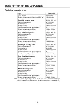
Page 28: ...w 188 Wh kg Front right heating zone 210 x 190 mm Minimum detection Ø 100 mm Nominal level 2100 W Booster level 2500 3000 W Standardised cookware category B Energy consumption ECcw 188 Wh kg Rear right heating zone 210 x 190 mm Minimum detection Ø 100 mm Nominal level 2100 W Booster level 2500 3000 W Standardised cookware category C Energy consumption ECcw 159 5 Wh kg Middle heating zone Ø 200 mm ...

Page 29: ...utomatically of 70 C II Stop Go The hob is in pause Bridge 2 cooking zones are combined Grill Function The Grill Function is activated Ventilation The cooling system is fully automatic The cooling fan starts with a low speed when the calories brought out by the electronic system reach a certain level The ventilation starts his high speed when the hob is intensively used The cooling fan reduces his...

Page 30: ...inless steel aluminium glass wood ceramic stoneware The induction heating zone adapts automatically the size of the pan With a too small diameter the pan doesn t work This diameter is varying in function of the heating zone diameter If the pan is not adapted to the induction hob the display will show U Sensitive touch Your ceramic hob is equipped with electronic controls with sensitive touch keys ...

Page 31: ...ossible to increase the power and the display shows U This symbol disappears when a pan is put on the heating zone If the pan is removed from the heating zone the operation is stopped The display shows U The symbol U disappears when the pan is put back to the heating zone The cooking continues with the power level set before After use switch the heat element off don t let the pan detection U activ...

Page 32: ...ntrol panel Display Start up the booster Slide to the end of the SLIDER P Or press directly on the end of the SLIDER Start up double booster Re press on the end of the SLIDER and P Stop the double booster Slide on the SLIDER P to 0 Stop booster Slide on the SLIDER 9 to 0 Power management The total cooking hob is equipped with an overall maximum of Booster power When the Booster function is activat...

Page 33: ...Timer Press key Timer display on Stop the time Press key from the timer 000 If several timers are activated repeat the process Egg timer function Egg timer is an independent function It stops as soon as a heating zone starts up If the egg timer is on and the hob is switched off the timer continues until time runs out Action Control panel Display Activate the hob Press key for 2 sec 0 Select the Ti...

Page 34: ...isplay Power level selection slide on the SLIDER 0 to 9 Stop Go function This function brakes all the hob s cooking activity temporarily and allows restarting with the same settings Start up stop the pause function Action Control panel Display Engage pause press II 2s II and control light on Stop the pause press II 2s previous settings Recall Function After switching off the hob it is possible to ...

Page 35: ... key for 2 sec 0 Activate the bridge Place a pan on one of the two zones that will be bridged and press simultaneously the corresponding selection keys 0 and or Automatically put a great pan on the blink 2 zones and press on the 2 SLIDER Increase bridge Slide on the SLIDER witch indicates the power 1 to 9 Stop the bridge Press simultaneously of the 2 cooking zones 0 Control panel locking To avoid ...

Page 36: ...Start up stop the grill function Action Control panel Display Engage the grill function press GRILL Stop the grill function press GRILL 0 Operating time limitation Each cooking zone is equipped with an operating time limitation the cooking zone is automatically switched off after a certain time without any change of settings This time is varying according to the selected power level as described i...

Page 37: ...ion cooking zone This noise doesn t mean any failure on the appliance and doesn t influence the cooking operating The composition of the pan base can affect the evenness of the cooking results and power reception by the inductors Only use pots and pans with smooth bases Rough bases will scratch the ceramic glass Where possible use pans with vertically straight side If a pan has angular sides induc...

Page 38: ...g up liquid diluted in a little water Then rinse with cold water and dry the surface thoroughly Highly corrosive or abrasive detergents and cleaning equipment likely to cause scratches must be absolutely avoided Do not ever use any steam cleaner or pressure washer Do not use any object that may scratch the ceramic glass Ensure that the pan is dry and clean Ensure that there are no grains of dust o...

Page 39: ...n t start up The cooking zone is still hot H The highest Booster level is set 9 The control panel displays U Refer to the chapter Keep warm The control panel displays II Refer to the chapter Stop Go The control panel displays or Er03 An object or liquid covers the control keys The symbol disappear as soon as the key is released or cleaned The control panel displays E2 The hob is overheated let it ...

Page 40: ...gasket The gasket supplied with the hob prevents the intrusion of liquids into the cabinet below It s installation has to be done carefully in conformity with the following drawing Fitting installing The cut out sizes are A B E F H KI9560 0SR 900 mm 520 mm 850 mm 490 mm 53 mm Don t throw your appliance with the household refuses Get in touch with the waste collection centre of your commune that is...

Page 41: ...ood air circulation of the electronic device If a drawer is placed under the hob avoid putting into this drawer flammable objects for example sprays or non heat resistant objects Materials which are often used to make worktops expand on contact with water To protect the cut out edge apply a coat of varnish or special sealant Particular care must be taken when applying the adhesive joint supplied w...

Page 42: ...derneath at the back of the hob casing To open the cover use a medium screwdriver Place it in the slits and open the cover calculated with the simultaneous factor following the standard EN 60 335 2 6 Connection of the hob For the various kinds of connection use the brass bridges which are in the box next the terminal Monophase 230V 1P N Put the 1st bridge between terminals L1 and L2 the 2nd bridge...

Page 43: ...LIDER ET DE REGLAGE DE LA MINUTERIE 50 MISE EN ROUTE 50 DETECTION DE RECIPIENT 51 INDICATEUR DE CHALEUR RESIDUELLE 51 FONCTION BOOSTER ET DOUBLE BOOSTER 52 FONCTION MINUTERIE 53 PROGRAMMATION D AUTOMATISME DE CUISSON 54 FONCTION STOP GO 54 FONCTION RAPPEL 54 FONCTION MAINTIEN AU CHAUD 55 FONCTION BRIDGE ET BRIDGE AUTOMATIQUE 55 VERROUILLAGE DU BANDEAU DE COMMANDE 55 FONCTION CHEF 56 FONCTION GRILL...

Page 44: ...ique commerciale ou industrielle Enlevez toutes les étiquettes et autocollants du verre vitrocéramique Ne pas transformer ou modifier l appareil La table de cuisson ne doit pas servir de support ou de plan de travail La sécurité n est assurée que si l appareil est raccordé à une terre de protection conforme aux prescriptions en vigueur Pour le raccordement au réseau électrique n utilisez pas de ra...

Page 45: ...ls peuvent devenir chauds De façon générale ne placez aucun objet métallique autre que les récipients de chauffe sur la surface vitrée En cas d enclenchement intempestif ou de chaleur résiduelle celui ci risquerait selon le matériau de chauffer de fondre ou de commencer à brûler Ne jamais couvrir l appareil d un chiffon ou d une feuille de protection Il pourrait devenir très chaud et prendre feu C...

Page 46: ... d aluminium ne touchent les zones chaudes Ces substances peuvent au refroidissement provoquer des cassures ou d autres modifications de la surface vitrocéramique Eteindre l appareil et enlevez les immédiatement de la zone de cuisson encore chaude attention risque de brûlures MISE EN GARDE Risque d incendie ne pas entreposer d objets sur la surface de cuisson Ne placez jamais de récipients chauds ...

Page 47: ... zone de cuisson Le fond de la casserole doit autant que possible couvrir la zone de cuisson Pour les utilisateurs portant un régulateur de rythme cardiaque le champ magnétique pourrait influencer son fonctionnement Nous recommandons de se renseigner auprès du revendeur ou du médecin N utilisez pas de récipients en matière synthétique ou en aluminium ils pourraient fondre sur des foyers encore cha...

Page 48: ...cw 188 Wh kg Zone avant droite 210 x 190 mm Détection minimum Ø 100 mm Puissance nominale 2100 W Puissance du booster 2500 3000 W Catégorie de la casserole standard B Consommation d énergie ECcw 188 Wh kg Zone arrière droite 210 x 190 mm Détection minimum Ø 100 mm Puissance nominale 2100 W Puissance du booster 2500 3000 W Catégorie de la casserole standard C Consommation d énergie ECcw 159 5 Wh kg...

Page 49: ...le est en pause Bridge 2 zones de cuisson sont combinées Fonction Grill La fonction Grill est activée Ventilation Le ventilateur de refroidissement a un fonctionnement entièrement automatique Il se met en route à petite vitesse dès que les calories dégagées par l électronique dépassent un certain seuil La ventilation enclenche sa seconde vitesse lorsque la table de cuisson est utilisée intensiveme...

Page 50: ...ium verre bois céramique grès terre cuite inox non ferro magnétique La zone de cuisson à induction prend automatiquement en compte la taille du récipient utilisé Avec un diamètre trop petit le récipient ne fonctionne pas Ce diamètre varie en fonction du diamètre de la zone de cuisson Lorsque le récipient n est pas adapté à la table de cuisson le symbole U reste affiché Touches sensitives Votre app...

Page 51: ...onctionne pas Lorsqu il n y a pas de récipient sur la zone de cuisson ou lorsque ce récipient est inadapté à l induction Dans ce cas il est impossible d augmenter la puissance et dans l afficheur le symbole U apparaît Le U disparaît lorsqu une casserole est posée sur le foyer de cuisson Si en cours de cuisson le récipient est enlevé de la zone de cuisson le fonctionnement est interrompu Dans l aff...

Page 52: ...ouble booster Action Bandeau de commande Afficheur Enclencher le booster glisser jusqu à la fin du SLIDER P ou appuyer directement sur la fin du SLIDER Enclencher le double booster ré appuyer sur la fin du SLIDER clignote avec P Stopper le double booster glisser sur le SLIDER P à 0 Stopper le booster glisser sur le SLIDER 9 à 0 Gestion de la puissance maximale L ensemble de la table de cuisson est...

Page 53: ...ur le temps s affiche Arrêt de la minuterie appuyé sur de la minuterie 000 Lorsque plusieurs minuteries sont activées il suffit de répéter l opération Minuterie utilisée hors cuisson La minuterie fonctionne indépendamment des foyers et se désactive dès la mise en route d une zone de chauffe Si elle est activée et que la table de cuisson est arrêtée la minuterie continue jusqu à ce que le temps imp...

Page 54: ...e glisser sur le SLIDER 0 à 9 Fonction Stop Go Cette fonction permet d interrompre temporairement la cuisson et de la réactiver avec les mêmes réglages Enclencher arrêter la fonction pause Action Bandeau de commande Afficheur Activer la pause appuyer sur II 2s II sur les afficheurs voyant pause allumé Stopper la pause appuyer sur II 2s animation des voyants les réglages précédent s affichent Fonct...

Page 55: ...pondantes 0 et ou Automatique poser une grande clignote casserole sur les 2 zones à bridger Sélectionner la puissance glisser sur le SLIDER correspondant à l affichage de la 1 à 9 puissance Arrêter le bridge appuyer simultanément sur les 2 touches de selection 0 des 2 zones combinées Verrouillage du bandeau de commande Pour éviter de modifier une sélection de la table de cuisson notamment dans le ...

Page 56: ...Activer la fonction Grill appuyer sur GRILL Stopper la fonction Grill appuyer sur GRILL 0 Limitation du temps de fonctionnement La table de cuisson est équipée d une limitation du temps de fonctionnement La durée d utilisation de chaque zone de cuisson dépend du niveau de puissance sélectionné Les temps indiqués correspondent à une durée de fonctionnement sans interruption ou modification des régl...

Page 57: ...ent en aucun cas un défaut de l appareil et n influent nullement sur son fonctionnement La qualité du fond de la casserole peut influencer l uniformité de la cuisson et le enregistrement de puissance de la casserole N utilisez que des casseroles et des poêmes à fond lisse Les bases rugueuses des casseroles et des poêles raient le verre Utilisez de préférence des sauteuses à bords droits Pour les p...

Page 58: ... conseillé pour la vitrocéramique N utilisez en aucun cas d appareils à vapeur ou à pression Ne pas utiliser d objets qui risqueraient de rayer la vitrocéramique tel que tampon abrasifs ou pointe de couteau N utilisez pas de produits de nettoyage abrasifs qui pourraient endommager l appareil Séchez l appareil avec un chiffon propre Enlevez immédiatement le sucre et les mets contenant du sucre QUE ...

Page 59: ...tomatiquement La commande de cuisson automatique ne s enclenche pas La zone de cuisson est encore chaude H Le niveau de cuisson maximum est enclenché 9 Le symbole U s affiche Se référer au chapitre Maintien chaud Le symbole II s affiche Se référer au chapitre Pause Le symbole ou Er03 s affiche Un objet ou un liquide recouvre les touches de la commande Le symbole disparaît une fois les touches libé...

Page 60: ...r la législation et les normes en vigueur dans son pays de résidence Mise en place du joint d étanchéité Le joint adhésif fourni avec l appareil permet d éviter toute infiltration dans le meuble Sa mise en place doit être effectuée avec un grand soin suivant le croquis ci dessous Ne jetez en aucun cas votre appareil avec les déchets ménagers Faites appel au service d enlèvement ou aux sites de dép...

Page 61: ...le chant de la découpe appliquer un vernis ou une colle spéciale N installer pas la table au dessus d un four non ventilé ou d un lave vaisselle Garantir entre le fond du caisson de l appareil un espace de 20 mm pour assurer une bonne circulation de l air de refroidissement de l électronique Si un tiroir se trouve sous le plan de cuisson éviter d y ranger des objets inflammables par exemple spray ...

Page 62: ...erre de protection Respectez le schéma de raccordement Le boîtier de raccordement se situe sous la plaque de cuisson Pour ouvrir le capot servez vous d un tournevis moyen Placez le dans les 2 fentes situées à l avant des 2 flèches Réseau Raccordement Diamètre câble Câble Calibre de protection 230V 50Hz 1 Phase N 3 x 2 5 mm H 05 VV F H 05 RR F 40 A 400V 50Hz 2 Phases N 4 x 1 5 mm H 05 VV F H 05 RR ...

Page 63: ......

Page 64: ...27290 0 K06 180025 02 ...

Reviews: