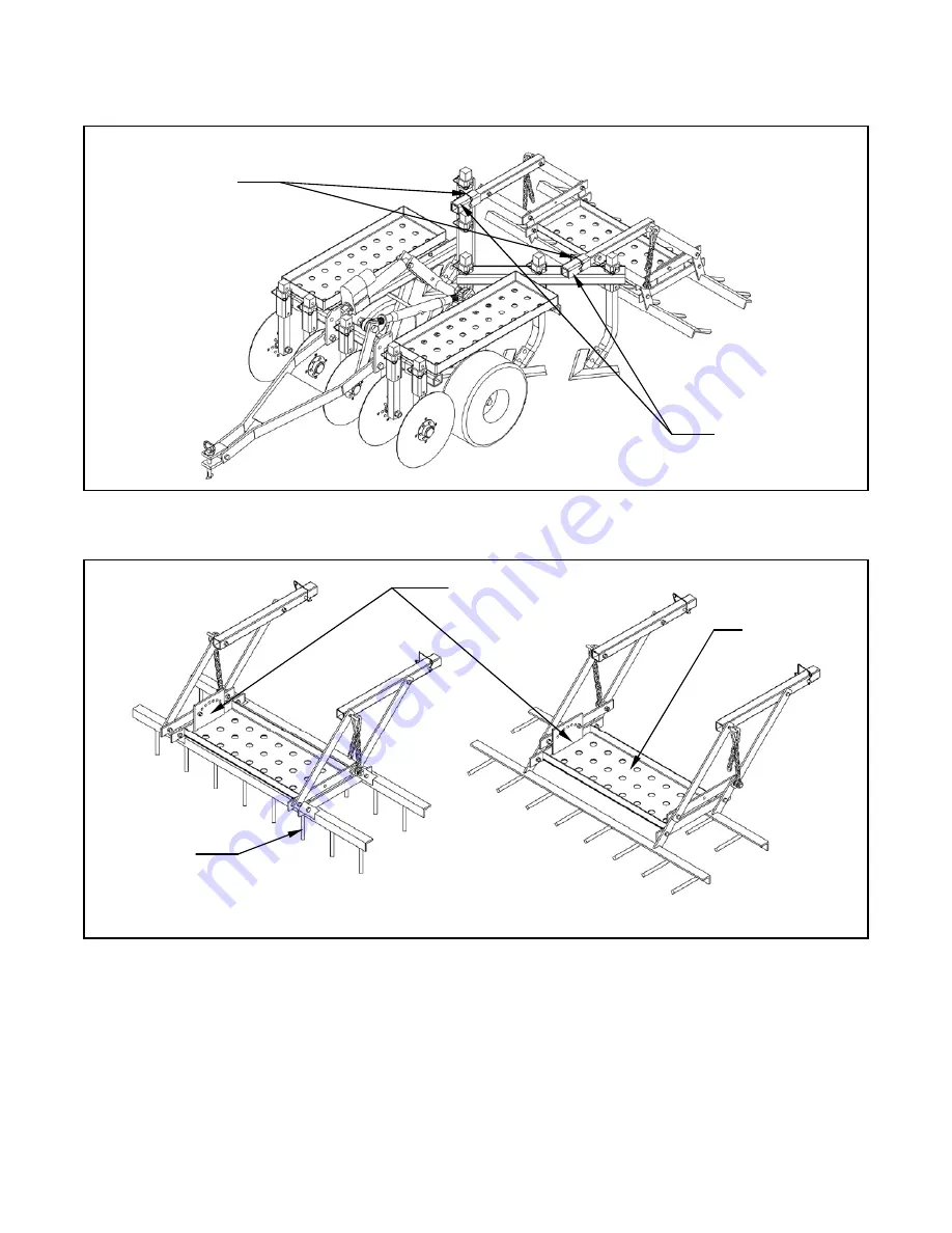
Wire Lock Pins
Attachment Receivers
Figure 2. – Drag Harrow Installation
Spike Tooth
Horizontal Spike Position
Vertical Spike Position
Weight Rack
Adjustment Plate – Seven Hole Positions
Figure 3. – Spike Tooth Positioning
2
Page 1: ... support tube 5 Position the hole on the free end of the tow links with the hole location on the support tube where the bolt was removed in the previous step 6 Insert the 3 8 x 2 1 4 bolt through the aligned holes and fasten with the nylon insert lock nut This location is a pivot point and should not be fully tightened 7 Hook the snap hooks on the appropriate eye bolts Snap Hook Chain Eye Bolt Sup...
Page 2: ...ck Pins Attachment Receivers Figure 2 Drag Harrow Installation Spike Tooth Horizontal Spike Position Vertical Spike Position Weight Rack Adjustment Plate Seven Hole Positions Figure 3 Spike Tooth Positioning 2 ...
Page 3: ...essure for different soil types or tillage depths The drag harrow also has the ability to contact the ground with the sweeps and coulters fully removed from the ground Note If additional pressure is desired weight can be added to the weight rack on the drag harrow The second adjustment that can be made to the drag harrow is the spike tooth angle There are seven different hole positions which resul...
Page 4: ...6013 Wire Lock Pin 2 2 222011 Safety Snap Hook 2 3 500025 Tow Link 4 4 500026 Support Tube 2 5 500027 Upper Link Flat 2 6 800004 Front Harrow Section 1 7 800005 Rear Harrow Section 1 8 800009 Harrow Frame 1 DRAG HARROW PARTS 1 4 3 2 5 8 6 1 3 5 7 4 ...