background image


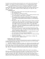
To provide correct pressure of the fuel supply to your stove, the tank outlet should be 

between 16” and 72” above the carburetor on the stove.  Do not exceed 72” above the 
carburetor as excessive head pressure could limit the carburetor’s ability to shut off fuel flow.  
Be sure the support system under the tank is safe and adequate as a full 300 gallon tank will 
weigh about 2000 lb. 
 

If you must install a tank below the stove, or above the recommended height, a lift pump 

and/or a level control valve must be fitted.  You will need to check local building codes 
regarding such installations. 


CONNECTIONS: 


There should be 2 valves on a typical installation: 1) a shut-off valve at the tank to allow 

service to any piping, or changing the main filter and  2) a shut-off valve close to the stove to be 
able to isolate the stove for any maintenance, and (if required by code) a fire valve right before 
the fuel pipe enters the building which would automatically shut off the oil supply in the 
unlikely event of the stove overheating.  Piping to the stove from the tank may be either steel or 
copper, but copper is preferred to prevent any rusting problems.  When making the fuel line 
connection with the copper line from the tank to the stove, it is best to have a gradual slope or 
“fall” on the line (i.e. no dips or kinks) so as to prevent any air bubbles or collection of dirt or 
other impurities.  A 3/8” diameter copper supply line is recommended and either compression 
type or flare type fitting may be used.  Finally, a good quality filter that also traps water should 
be placed at the tank to ensure a good, clean supply of oil to your stove.  The carburetor on the 
stove is equipped with a screen-type filter but it is not intended for use as the primary filter. 
 

SECTION 4 

Lighting, carburetor adjustments, and draft stabilizer adjustments 


PRE-LIGHTING CHECKS: 


The installation should be inspected to ensure that the work is complete and the 

workmanship is satisfactory.  No stove should be lit if any part of the installation does not 
comply with the relevant standards and regulations. 
 

The oil tank should be examined to confirm there is a supply of the correct grade of oil, 

that a filter and a working isolation valve are fitted.  Having verified that the oil pipe work up to 
the stove is complete and that the fire valve (if used) is closed, the tank isolation valve should 
be opened and the pipe work inspected for leaks.  The pipe into the inlet of the metering valve 
should be uncoupled, the shut off valve opened and a minimum of one quart of oil collected 
into a suitable receptacle.  If dirt or water is present in this sample, additional oil should be 
allowed through the pipe work until it is free from contaminates.  The fuel pipe work should be 
reassembled and all connections checked for leaks and tightened as necessary. 
 

For 7” Burner Models: Laying on top of the catalyst inside your Oil Classic 7” burner 

model stove is a stainless steel top burn ring.  It is important that the ring be in the proper 
position.  It comes in the proper position from the factory.  Should the height of this ring 
change, it is easy to re-adjust by bending the three tabs that rest on the catalyst top up or 
down.  It is very important that the “cupped” part of the ring is facing up (as if it would hold 
water).  The stove will not burn properly if the ring is face down.  Locate the two continuous 
rows of air holes circling the burner top.  The top ring tabs should set on the catalyst top so 
that the outer edge of the ring comes out right between those two rows of air holes.


LIGHTING: 


Initial lighting should be undertaken by a qualified technician, with a suitable probe-

type manometer for checking the flue pressure.  Although adjusting the draft stabilizer by “feel” 

Summary of Contents for OC-10

Page 1: ...ove it is recommended that the installation be done by a qualified installer familiar with fuel oil stoves preferably an NFI Certified National Fireplace Institute expert We recommend contacting local building or fire officials in your area regarding restrictions and installation inspection requirements Please read this entire manual before attempting installation or operation of this appliance Im...

Page 2: ...orner of the pedestal base should these adjustments be necessary Place a level on top of the pedestal base both directions and adjust until level This unit has been tested to U L 307A and is approved for installation and use in manufactured homes There are some special considerations when installing into a mobile or manufactured home For model OC 10 10 burner the flue system must consist of a 6 di...

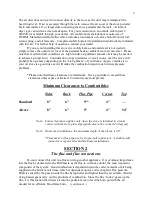
Page 3: ...t will make the combustion impervious to house pressure problems Please note that these clearances are minimums It is a good idea to exceed these clearances unless space is limited Common sense must prevail Minimum Clearances to Combustibles Sides Back Flue Pipe Corner Top Standard 8 6 9 4 Alcove 8 6 9 4 54 Note Corner clearance applies only when the stove is installed in a room corner with the st...

Page 4: ... must be removed and the draft stabilizer adjusted Its purpose is to allow more or less air to travel into the flue to compensate for a change in the flue draft Adjustment of the draft stabilizer will be discussed in Section 4 SECTION 3 Fuel tank installation and fuel line connections OIL Your Kuma Oil Classic comes with a carburetor set for an average of a 2 35 cc viscosity rating You should be a...

Page 5: ...g carburetor adjustments and draft stabilizer adjustments PRE LIGHTING CHECKS The installation should be inspected to ensure that the work is complete and the workmanship is satisfactory No stove should be lit if any part of the installation does not comply with the relevant standards and regulations The oil tank should be examined to confirm there is a supply of the correct grade of oil that a fi...

Page 6: ...r should begin burning blue at flame base and yellow at flame tip At this point a pressure check should be made and the draft stabilizer adjusted to within the recommended pressure setting range see draft pressure chart on page 7 8 Run the stove for at least 30 minutes on low or medium to allow the whole stove and chimney to come up to operation temperature 9 Turn the control knob to setting 1 and...

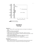
Page 7: ...tes before re starting following the lighting instructions in this manual If you have any questions about the operation of your Oil Classic please check the trouble shooting section of this manual or call your dealer DRAFT STABILIZER ADJUSTMENTS After removing the rear draft stabilizer access cover the 7 x 7 square cover in the middle of the stove back you will see that the draft stabilizer has a ...

Page 8: ... stove interior and drip pan Lightly brush off catalyst and inspect for deterioration replace if necessary Check all gaskets rope seal around door window seal check for loose glass no need to remove access panel gaskets Check oil tank for damage or leaks and clean or replace main tank filter Check all lines and connections for leaks or deterioration A draft reading should be taken for low and high...

Page 9: ... near fuel inlet SECTION 6 Trouble shooting guide CONDITION 1 Oil present in burner with the carburetor in off position 2 No oil in burner bottom after carburetor is turned on 3 Flame smoky when lit 4 Flame smoky when burning low 5 Flame smoky when burning high 6 Flame goes out on low 7 Flame goes out in high winds 8 Burner goes out and will not re light 9 Flame is noisy buzzing or roaring or sepa...

Page 10: ...d draft stabilizer may need to be installed in the pipe as well to compensate A wind directional cap or vacuum cap may be helpful to prevent wind gusts and down drafts from affecting pressure 8 No oil in tank Valve in fuel supply line shut inadvertently Fuel supply blocked plugged filter frozen water Carburetor on off lever tripped 9 Stove door having been open for a while and then shut a roaring ...

Page 11: ...l line supplied with stove 2 years Warranty does not cover gold plated door surface normal maintenance items such as paint glass and gasket This warranty does not apply in cases of abuse mishandling unauthorized repair alterations failures or operating difficulties due to misuse accident misapplication improper installation improper maintenance or service Kuma Stoves reserves the right under this ...

Reviews: