

© 2019 Kleinbongartz & Kaiser oHG | All rights reserved.
Unauthorized copying or distribution without written permission is strictly prohibited. Subject to technical changes as well as typesetting and printing errors.
KUKKO Werkzeugfabrik | Kleinbongartz & Kaiser oHG
Heinrich-Hertz Str. 5 | 40721 Hilden | Germany | Phone +49 2103 9754-300 | Fax +49 2103 9754-310 | [email protected] | kukko.com
KUKKO //
Pull forward
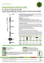
8-1-B, 8-1-F/8-2-K, 8-2-M
HYDRAULIC SCREWS/RAMS FOR KUKKO PULLERS, 15 AND 20-TON HYDRAULIC SCREWS
For pulling particularly tight bearings, gears, discs, etc.
The great advantage of these powerful hydraulic screws is their ability to quickly
and easily remove tight-fitting parts.
The mechanicle spindle can be exchanged by the hydraulic spindle which fits to the
puller.
Assembly procedure:
Screw the thrust bolt (d) into the taphole in the hydraulic ram (c). Slide the hollow
spindle (e) over the thrust bolt, and insert it into the opening at the bottom of the
hydraulic ram.
Turn the breechlock nut (f) onto the threaded end of the ram, and
tighten the side screw.
Push the thrust pad (g) over the end of the thrust bolt (d).
Operation:
Use the spanner (b) to turn the screw into the puller head until the thrust pad is
securely seated on the end of the shaft. Now, turn the T-handle (a) to start the
hydraulic action.
Turning must be done by hand. The handle is sized to ensure that the maximum
permissible torque can not be exceeded.
Back off the T-handle (a) after each operation.
Caution:
Perfect alignment of the hydraulic puller with the part to be withdrawn is very
important. Misalignment will create extra bending forces and damage the tool or
cause accidents. Before operating under pressure, part and puller should be wrapped
securely in a protective blanket (UFP-1, UFP-2 oder UFP-3). Forces exerted must be
controlled carefully during the pulling action. The maximum permissible load will be
reached at a torque of 45 Nm (8-1) or 30 Nm (8-2) and must not be exceeded.
SAFETY INSTRUCTIONS AND CARE TIPS
a
c
d
e
f
g
b
Always wear suitable personal protec-
tive equipment, including protective
goggles.
Always wrap the pulling tool and the workpiece in a
protective blanket as a precaution against the poten-
tial effects of sudden release.
Art.No.: UFP-1, UFP-2, UFP-3
Puller spindle maintenance:
The spindle must always be kept well lubricated. We
recommend the use of KUKKO special sliding grease for pressure spindle (Art. No.: 699915 and
699975), or KUKKO Bio Multi Oil (Art. No.: 699990). A tube of
KUKKO special sliding grease for pressure spindle is free with every order of an
original KUKKO puller.
Art.-
No.
mm
mm
max.
t
max.
Nm
8-1-B
250
R1“
10
15
45
7,65
8-1-F
350
R1“
10
15
45
7,70
8-2-K
250
G 1 1/8“
10
20
30
9,90
8-2-M
350
G 1 1/8“
10
20
30
10,00
INSTRUCTION MANUAL


